Often church sound folk are looking for the cheapest possible solution for recording their services. In this case, they want to use a low-end voice recorder and record directly from the mixing board.
There are a number of challenges with this. For one, the voice recorder has no Line input – it only has a Mic-input. Another challenge is the AGC on the recorder which has a tendency to crank the gain way up when nobody is speaking and then crank it way down when they do speak.
On the first day they presented this “challenge” they simply walked up (at the last minute) and said: “Hey, plug this into the board. The guys at Radio Shack said this is the right cable for it…”
The “right cable” in this case was an typical VCR A/V cable with RCA connectors on both ends. On one end there was a dongle to go from the RCA to the 1/8th inch stereo plug. The video part of the cable was not used. The idea was to connect the audio RCA connectors to the tape-out on the mixer and plug the 1/8th inch end of things into the Mic input on the voice recorder.
This by itself was not going to work because the line level output from the mixer would completely overwhelm the voice recorder’s mic input– but being unwilling to just give up, I found a pair of RCA-1/4 inch adapters and plugged the RCA end of the cable into a pair of SUB channels on the mixer (in this case 3 & 4). Then I used the sub channel faders to drop the line signal down to something that wouldn’t overwhelm the voice recorder. After a minute or two of experimenting (all the time I had really) we settled on a setting of about -50db. That’s just about all the way off.
This worked, sort of, but there were a couple of problems with it.
For one, the signal to noise ratio was just plain awful! When the AGC (Automatic Gain Control) in the voice recorder cranks up during quiet passages it records all of the noise from the board plus anything else it can get it’s hands on from the room (even past the gates and expanders!).
The second problem was that the fader control down at -50 was very touchy. Just a tiny nudge was enough to send the signal over the top and completely overload the little voice recorder again. A nudge the other way and all you could get was noise from the board!
(Side note: I want to point out that this is a relatively new Mackie board and that it does not have a noise problem! In fact the noise floor on the board is very good. However the voice recorder thinks it’s trying to pick up whispers from a quiet room and so it maxes out it’s gain in the process. During silent passages there is no signal to record, so all we can give to the little voice recorder is noise floor — it takes that and adds about 30db to it (I’m guessing) and that’s what goes onto it’s recording.)
While this was reportedly a _HUGE_ improvement over what they had been doing, I wasn’t happy with it at all. So, true to form, I set about fixing it.
The problem boils down to matching the pro line level output from the mixer to the consumer mic input of the voice recorder.
The line out of the mixer is expecting to see a high input impedance while providing a fairly high voltage signal. The output stage of the mixer itself has a fairly low impedance. This is common with today’s equipment — matching a low impedance (relatively high power) output to one (or more) high impedance (low power, or “bridging”) input(s). This methodology provides the ability to “plug anything into anything” without really worrying too much about it. The Hi-z inputs are almost completely un-noticed by the Low-z outputs so everything stays pretty well isolated and the noise floor stays nice and low… but I digress…
On the other end we have the consumer grade mic input. Most likely it’s biased a bit to provide some power for a condenser mic, and it’s probably expecting something like a 500-2500 ohm impedance. It’s also expecting a very low level signal – that’s why connecting the line level Tape-Out from the mixer directly into the Mic-Input completely overwhelmed the little voice recorder.
So, we need a high impedance on one one end to take a high level line signal and a low impedance on the other end to provide a low level (looks like a mic) signal.
We need an L-Pad !
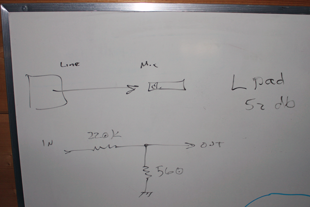
As it turns out, this is a simple thing to make. Essentially an L-Pad is a simple voltage divider network made of a couple of resistors. The input goes to the top of the network where it sees both resistors in series and a very high impedance. The output is taken from the second resistor which is relatively small and so it represents a low impedance. Along the way, the voltage drops significantly so that the output is much lower than the input.
Another nifty thing we get from this setup is that any low-level noise that’s generated at the mixer is also attenuated in the L-Pad… so much so that whatever is left of it is essentially “shorted out” by the low impedance end of the L-Pad. That will leave the little voice recorder with a clean signal to process. Any noise that shows up when it cranks up it’s AGC will be noise it makes itself.
(Side note: Consider that the noise floor on the mixer output is probably at least 60 db down from a nominal signal (at 0 db). Subtract another 52 db from that and the noise floor from that source should be -112 db! If the voice recorder manages to scrape noise out of that then most of it will come from it’s own preamp etc…)
We made a quick trip to Radio Shack to see what we could get.
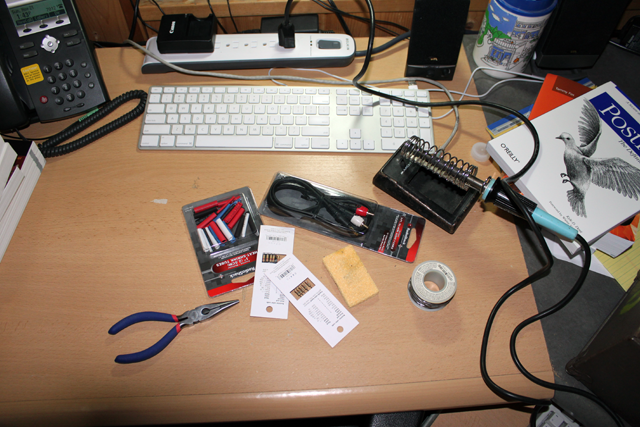
To start with we picked up an RCA to 1/8th inch cable. The idea was to cut the cable in the middle and add the L-Pad in line. This allows us to be clear about the direction of signal flow– the mixer goes on the RCA end and the voice recorder goes on the 1/8th inch end. An L-Pad is directional! We must have the input on the one side and the output on the other side. Reverse it and things get worse, not better.
After that we picked up a few resisters. A good way to make a 50db L-Pad is with a 33K Ω resistor for the input and a 100 Ω resistor for the output. These parts are readily available, but I opted to go a slightly different route and use a 220K Ω resistor for the input and a 560 Ω resistor for the output.
There are a couple of reasons for this:
Firstly, a 33K Ω impedance is ok, but not great as far as a “bridging” input goes so to optimize isolation I wanted something higher.
Secondly, the voice recorder is battery powered and tiny. If it’s trying to bias a 100 Ω load to provide power it’s going to use up it’s battery much faster than it will if the input impedance is 560 Ω. Also 560 Ω is very likely right on the low end of the impedance of the voice recorder’s input so it should be a good match. It’s also still low enough to “short out” most of the noise that might show up on that end of things for all intents and purposes.
Ultimately I had to pick from the parts they had in the bin so my choices were limited.
Finally I picked up some heat-shrink tubing so that I could build all of this in-line and avoid any chunky boxes or other craziness.
Here’s how we put it all together:
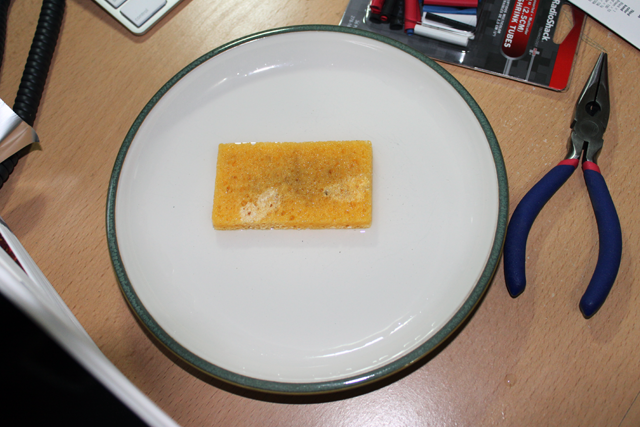
1. Heat up the old soldering iron and wet the sponge. I mean old too! I’ve had this soldering iron (and sponge) for close to 30 years now! Amazing how long these things last if you take care of them. The trick seems to be – keep your tip clean. A tiny sponge & a saucer of water are all it takes.
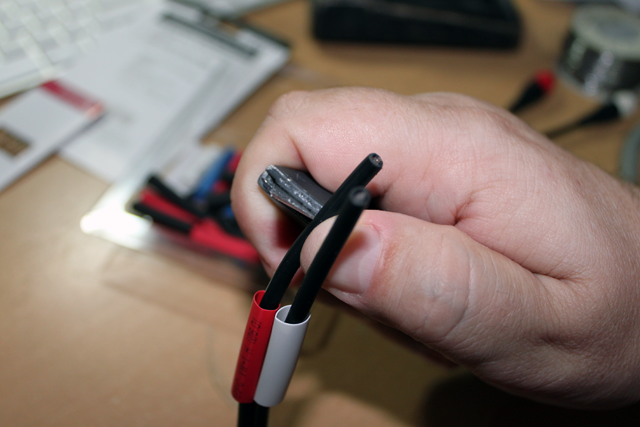
2. Cut the cable near the RCA end after pulling it apart a bit to provide room to work. Set the RCA ends aside for now and work with the 1/8th in ends. Add some short lengths of appropriately colored heat-shrink tubing and strip a few cm of outer insulation off of each cable. These cables are CHEAP, so very carefully use a razor knife to nick the insulation. Then bend it open and work your way through it so that you don’t nick the shield braid inside. This takes a bit of finesse so don’t be upset if you have to start over once or twice to get the hang of it. (Be sure to start with enough cable length!)
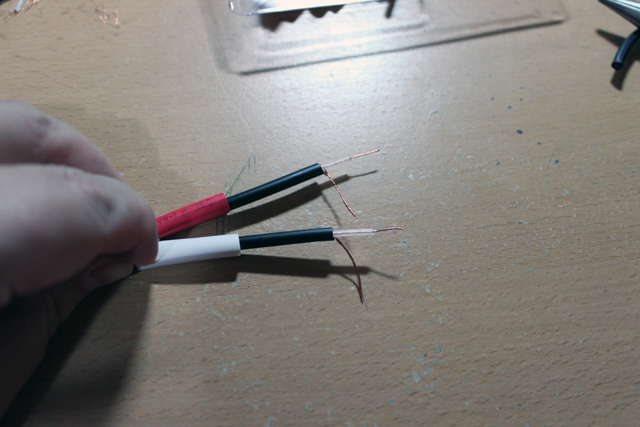
3. Twist the shield braid into a stranded wire and strip about 1 cm of insulation away from the inner conductor.
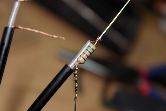
4. Place a 560 Ω resistor along side of the inner conductor. Twist the inner conductor around one lead of the resistor, then twist the shield braid around the other end of the resistor. Then solder these connections in place. Use caution — the insulation in these cables is very sensitive to heat. Apply the tip of your soldering iron to the joint as far away from the cable as possible and then sweat the solder toward the cable from there. This allows you to get a good joint without melting the insulation. Do this for both leads.
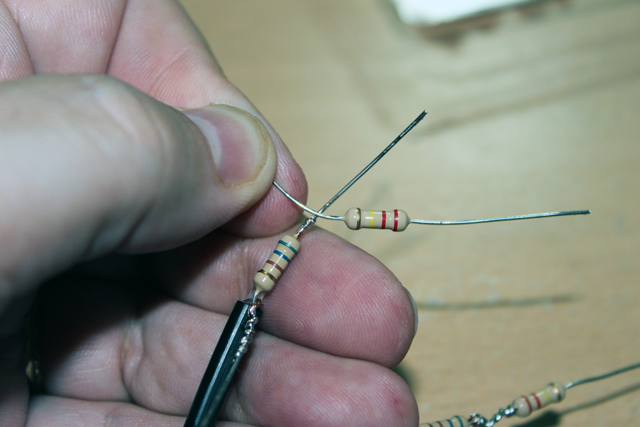
5. The 560 Ω resistors are now across the output side of our L-Pad cable. Now we will add the 220K Ω series resistors. In order to do this in-line and make a strong joint we’re going to use an old “western-union” technique. This is the way they used to join telegraph cables back in the day – but we’re going to adapt it to the small scale for this project. To start, cross the two resistor’s leads so that they touch about 4mm from the body of each resistor.
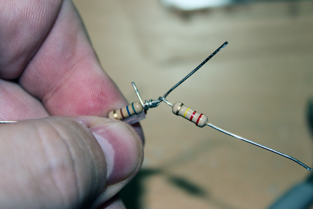
6. Holding the crossing point, 220K Ω resistor, and 560 Ω lead in your right hand, wind the 220K Ω lead tightly around the 560 Ω lead toward the body of the resistor and over top of the soldered connection.
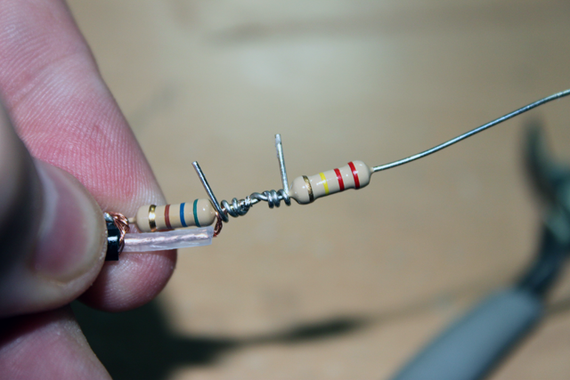
7. Holding the 560 Ω resistor and cable, wind the 560 Ω resistor’s lead tightly around the 220K Ω resistor’s lead toward the body of the resistor.
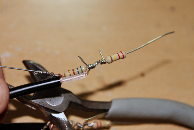
8. Solder the joint being careful to avoid melting the insulation of the cable. Apply the tip of your soldering iron to the part of the joint that is farthest from the inner conductor and sweat the solder through the joint.
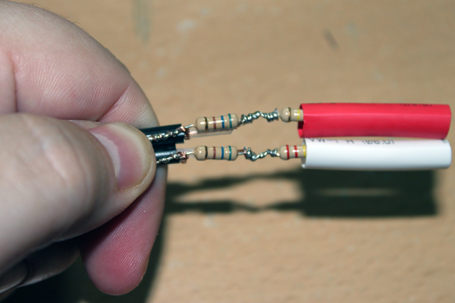
9. Clip of the excess resistor leads, then slide the heat-shrink tubing over the assembly toward the end.
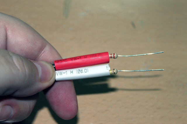
10. Slide the inner tubing back over the assembly until the entire assembly is covered. The tubing should just cover 1-2 mm of the outer jacket of the cable and should just about cover the resistors. The resistor lead that is connected to the shield braid is a ground lead. Bend it at a right angle from the cable so that it makes a physical stop for the heat-shrink tubing to rest against. This will hold it in place while you shrink the tubing.
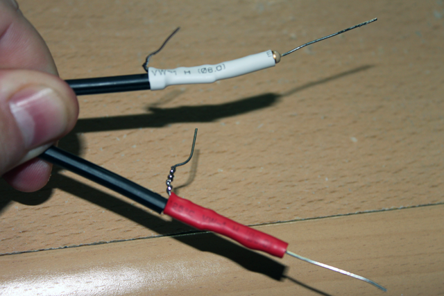
11. Grab your hair drier (or heat gun if you have one) and shrink the tubing. You should end up with a nice tight fit.
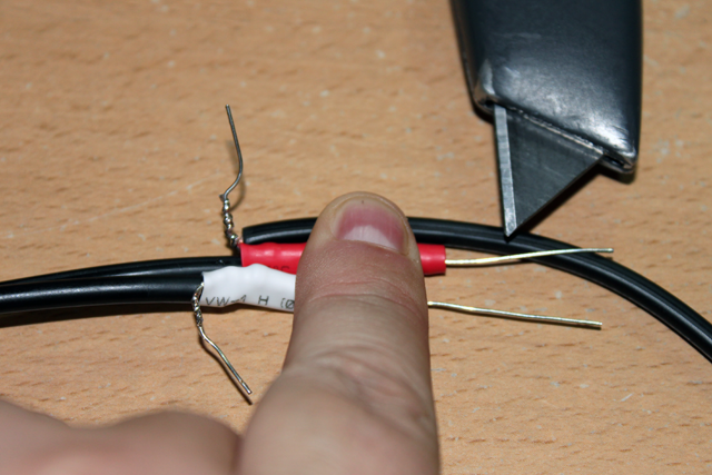
12. Grab the RCA end of the cable and lay it against the finished assembly. Red for red, and white for white. You will be stripping away the outer jacket approximately 1 cm out from the end of the heat-shrink tubing. This will give you a good amount of clean wire to work with without making the assembly too long.
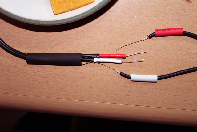
13. After stripping away the outer jacket from the RCA side and prepping the shield braid as we did before, strip away all but about 5mm of the insulation from the inner conductor. Then slide a length of appropriately colored heat shrink tubing over each. Get a larger diameter piece of heat-shrink tubing and slide it over the 1/8 in plug end of the cable. Be sure to pick a piece with a large enough diameter to eventually fit over both resistor assemblies and seal the entire cable. (Leave a little more room than you think you need.)
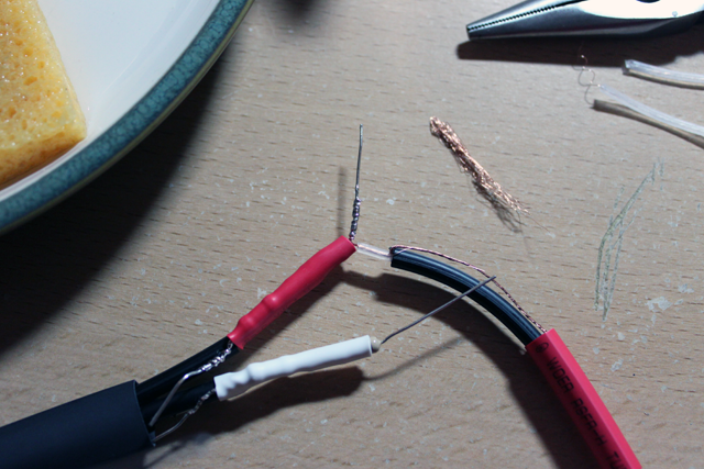
14. Cross the inner conductor of the RCA side with the resistor lead of the 1/8th in side as close to the resistor and inner conductor insulation as possible. Then wind the inner conductor around the resistor lead tightly. Finaly, solder the joint in the usual way by applying the tip of your soldering iron as far from the cable as possible to avoid melting the insulation.
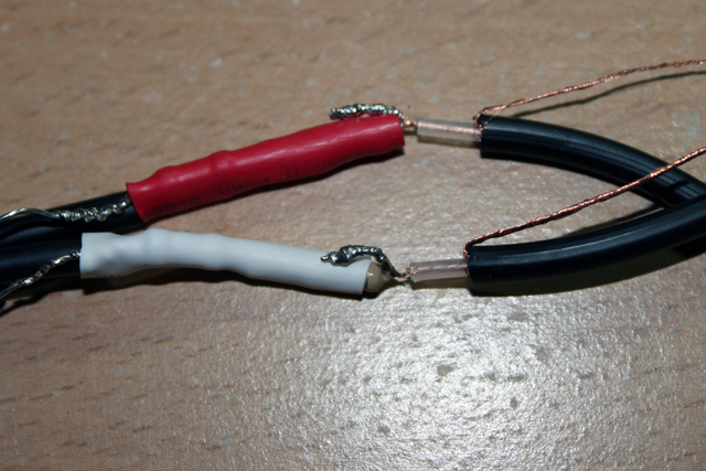
15. Bend the new solder joints down flat against the resister assemblies and clip off any excess resistor lead.
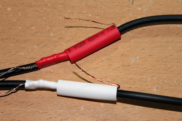
16. Slide the colored heat-shrink tubing down over the new joints so that it covers part of the resistor assembly and part of the outer jacket of the RCA cable ends. Bend the shield braid leads out at right angles as we did before to hold the heat-shrink tubing in place. Then go heat them up.
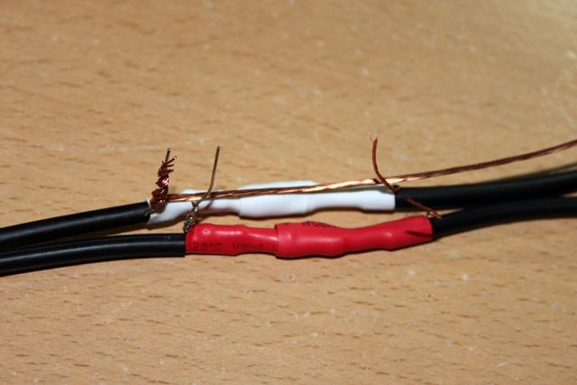
17. Now we’re going to connect the shield braids and build a shield for the entire assembly. This is important because these are unbalanced cables. Normally the shield braids provide a continuous electrical shield against interference. Since we’ve stripped that away and added components we need to replace it. We’ll start by making a good connection between the existing shield braids and then we’ll build a new shield to cover the whole assembly. Strip about 20 cm of insulation away from some stranded hookup wire and connect one end of it to the shield braid on one end of the L-Pad assembly. Lay the rest along the assembly for later.
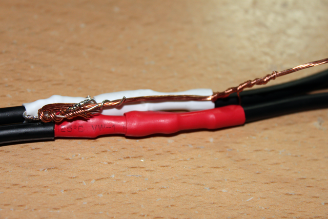
18. Connect the remaining shield braids to the bare hookup wire by winding them tightly. Keep the connections as neat as possible and laid flat across the resistor assembly.
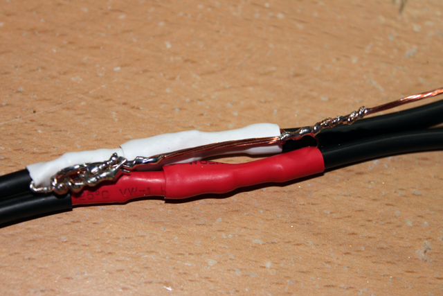
19. Solder the shield connections in place taking care not to melt the insulation as before.
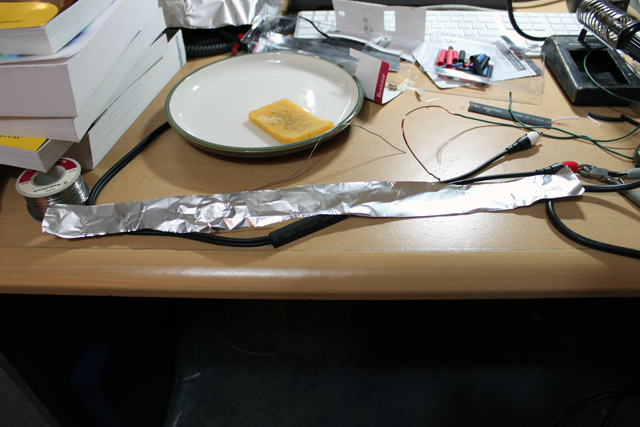
20. Cut a strip of ordinary aluminum foil about half a meter long and about 4 cm wide. This will become our new shield. It will be connected to the shields in the cable by the bare hookup wire we’ve used to connect them together.
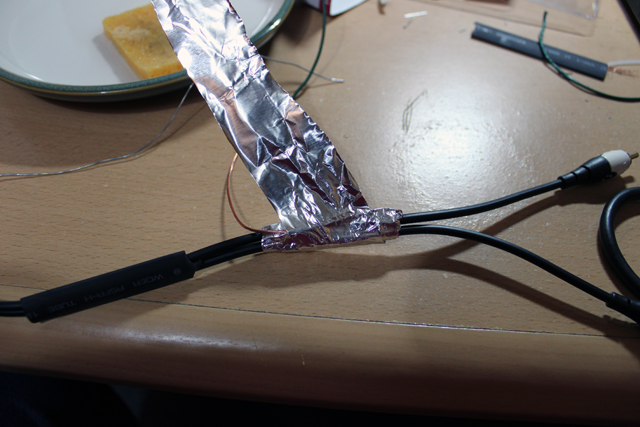
21. Starting at the end of the assembly away from the shield lead, wind a layer of foil around the assembly toward the shield lead. On each end of the assembly you want to cover about 5-10 mm of the existing cable so that the new shield overlaps the shield in the cable. When you reach that point on the end with the shield lead, fold the shield lead back over the assembly and the first layer of foil. Then, continue winding the foil around the assembly so that you make a second layer back toward where you started.
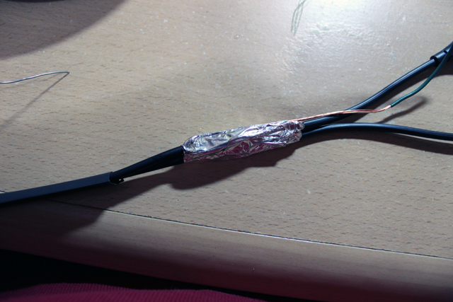
22. Continue winding the shield in this way back and forth until you run out of foil. Do this as neatly and tightly as possible so that the final assembly is compact and relatively smooth. You should end up with about 3-5 layers of foil with the shield lead between each layer. Finally, solder the shield lead to itself on each end of the shield and to the foil itself if possible.
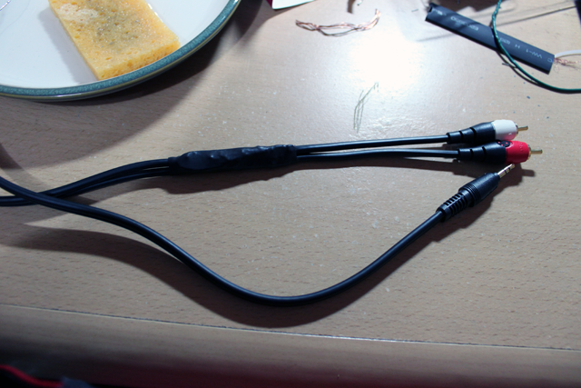
23. Clip off any excess shield lead. Then push (DO NOT PULL) the large heat-shrink tubing over the assembly. This may take a little time and effort, especially if the heat-shrink tubing is a little narrow. It took me a few minutes of pushing and massaging, but I was able to get the final piece of heat-shrink tubing over the shield assembly. It should cover about an additional 1 cm of cable on each end. Heat it up with your hair drier (or heat gun if you have it) and you’re done!
24. If you really want to you can do a final check with an ohm meter to see that you haven’t shorted anything or pulled a connection apart. If your assembly process looked like my pictures then you should be in good shape.
RCA tip to RCA tip should measure about 441K Ω (I got 436K).
RCA sleve to RCA ring should measure 0 Ω. (Shields are common).
RCA tip to RCA ring (same cable) should measure 220.5KΩ (I got 218.2K).
RCA sleve to 1/8th in sleve should measure 0 Ω.
RCA Red tip to 1/8th in tip should be about 220K Ω.
RCA Red tip to 1/8th in ring should be about 1K Ω more than that.


