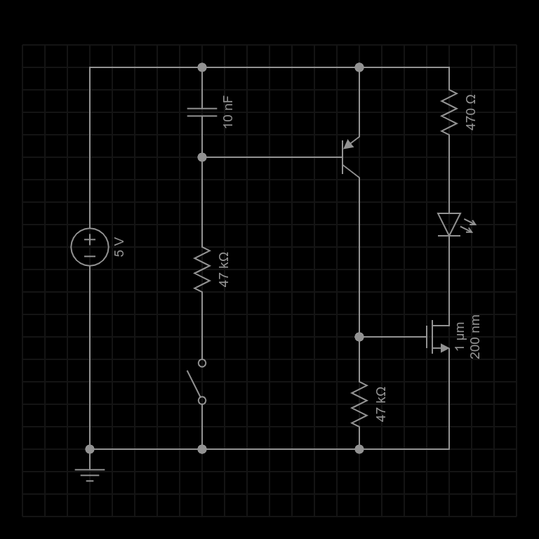
I thought “Ok, so let’s throw some parts at this thing and see if it works like the simulation…” and so I did:
As it turns out, I had a few different parts laying around the bench and using those would be easier than hunting down the specific values I had in my original simulation… those values aren’t critical really, so I just used what was already lying on the bench and updated the schematic in EveryCircuit to match:
Built up on the breadboard it looked like this:
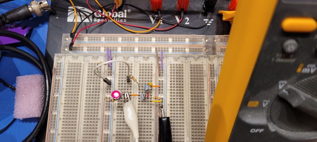
I find that with a little effort and creative thought it’s not difficult to get breadboard layouts to closely resemble schematic diagrams… and from there it’s not too much of a leap to get to what the prototype(s) and final build(s) will resemble.
A clockwise tour of the circuit on the breadboard…
Here you can see from top to bottom on the breadboard matching roughly from left to right on the schematic: There is a 47K input resistor that I’ve connected to a white wire that will act as the switch.
I describe that as a “wire” so that I can reserve the word “jumper” for the short color coded jumpers I use to make patches between segments of the breadboard. These are fantastic, by the way, because they are color coded for the number of points they span. This saves a lot of time when building up more complex circuitry or trying to trace where one or more of these jumpers go…
See the red jumper connecting 2 points away, and the orange 3, and so forth… very nice. I bought a bunch of boxes of these and I use them all the time. They’re so cheerful and perky. Full of potential – like a fresh box of colored pens and a new graph pad. I love that… but I digress.
You can see the input resistor go directly to the base of the PNP transistor, and on the back side of that transistor you can see the filter capacitor between base and emitter; an orange jumper connecting that to the positive rail 3 points away.
Moving down from there we come to the MOSFET acting as a switch. A red jumper connecting the collector of the input transistor to the gate of the switching MOSTFET and then from there you can see another 47K resistor pulling that down to the negative rail on the right.
In parallel with that a yellow jumper connects the source of the MOSFET to the negative rail (which will be common ground)… so that the other side of the switch is a typical “open drain” version of the “open collector” type of switch. The key idea being that it’s either open, or connected to ground.
Speaking of the “open drain” you can find an orange jumper crossing the centerline gap to the left and acting as the “output” of the circuit. Over on the left side you see couple of header pins stuck in the breadboard as a test point connector of sorts and then a panel mount LED connected on it’s other side to the positive rail through a 470 ohm resistor. (It was laying right there, and I didn’t care about the LED being a little bit dimmer, so I just went with it!)
You may have a little trouble spotting the header pins because there is a white alligator clip chomping on them… and if you look over to the right you’ll see a black alligator clip chomping on another set of pins plugged into the negative rail. These two clip leads make it easy to keep the DVM in circuit to measure the voltage across the output of the circuit… that way we can see just a bit more detail than whether the LED is on or off.
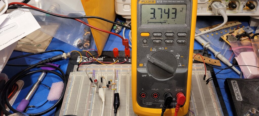
Testing Sketchy with a floating input
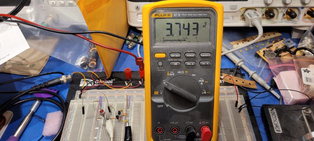
The guess is that the tuner controls the status line as an open-collector type of output. This means that the long wire running from the shack out to the tuner would see a very high impedance and would be essentially “floating” whenever the open collector is “off” at the tuner.
In this test you can see that the white input wire is hanging in the air on the left. The voltage at the output of our circuit is about an LED drop down from the positive rail… I guess because the DVM pulls just enough current to see that drop. 1.256v = 5 – 3.743
The LED is off… so all is well.
Testing Sketchy with a “human antenna” input
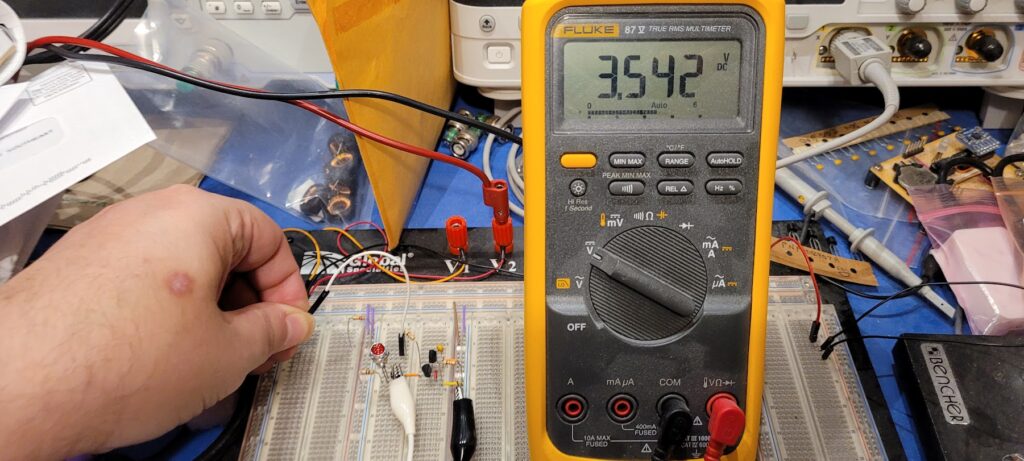
A long “floating” wire seems a lot like an antenna that might pick up all kinds of noise or even some stray RF (this is going to an antenna tuner after all). We want to make sure the circuit isn’t sensitive to that so we put in a filter capacitor across the BE junction of the input transistor. The idea is that the input resistor and the capacitor make a low pass filter that will reject almost anything that isn’t close to DC.
Connecting myself to the input wire to give it some “extra length” we can see that I do inject some noise; but not enough to cause the circuit to really switch. The LED stays off, and the voltage across the output only goes down by a couple hundred millivolts. That’s enough to see on a DVM, but not enough to matter when switching LEDs on and off. (Nor even enough for any logic circuit that might come later to care about it either.) 201mv = 3.743 – 3.542
Testing Sketchy with the input pulled high
Another design spec is that the circuit should be happy with a TTL input. So, connecting the input to the positive rail (+5V) we get the same result as the floating input: The output is off as expected!!
Testing Sketchy with the input pulled low
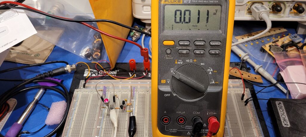
Testing the other side of the TTL input spec as well as the open collector input spec, we pull the input low by connecting it to the negative (ground / common) rail. As expected, the output goes to ground and the LED comes on!! Not only on, but VERY on… 11mv measured across the output.
This is a benefit of using a good switching MOSFET vs a bipolar transistor for this kind of output (open drain/collector). The “closed circuit” or “on” condition of the output with the MOSFET will have a much lower voltage than you can get from a bipolar transistor. Definitely closer to ground.
Testing Sketchy with the input pulled low weakly
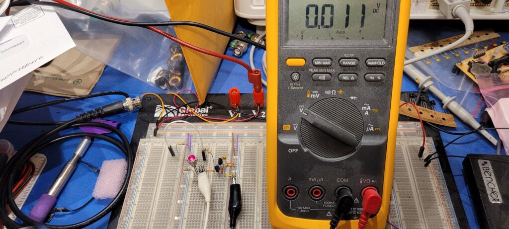
Finally, since our theory about the status line problem is that it may be oxidized at the connector near the tuner, we tested again with a high resistance in place. In this case, a 220K resistor to simulate whatever that unwelcome resistance might be out there. Again success! The LED is fully on just as if the input had been pulled hard to ground.
Qapla’ !!