A while back we replaced the SGC-237 at the feed point of the big loop. Since then, the controller has been a bit sketchy. The indicator for a good tuning solution is intended to light either the yellow panel LED or the green panel LED; but since the upgrade the best it seems to manage is a bright or dim yellow.
I’m not sure what’s going on there, but I have a few theories. One is that the junction for the control indicator line in the box under the tree might be a bit oxidised causing extra resistance in the line. Another is that the design of the SGC-237 might have changed with the unit I have now, or that perhaps it never really was an open collector on the tuner end (that was a guess afterall). Another is that I just got lucky with the first design and that the long lead length might have something to do with my indicator not-quite getting the clear signal it needs.
I did measure the voltage across the input while the system was up doing it’s WSPR thing (where it must tune with each band change)… and I observed that the voltage from the indicator to ground seemed to get no higher than about 4V and no lower than about 3.2V… that’s weird, and suspiciously close to a silicon junction drop (about 0.8V)… almost as suspicious as frog’s breath… but of course, nothing is as suspicious as frog’s breath. Whatever is going on there has to do with how the indicator circuitry in my controller is interacting with the tuner through the controller cable and the junction box in the middle.
Anyway– at some point I will go out there and lie on the ground and “improve” the connections in the box. In the meantime, since the tuner seems to otherwise work just fine, I’m looking for a quick fix to get my indicator working properly again and generally make it more robust.
So, based on the idea that it’s probably some thing that looks reasonably like an open collector at the tuner end, or that even if it’s a TTL signal I might be able to interpret it like an open collector… I designed a circuit to clean up the indicator signal and make it FIRMLY on or off in an open collector manner.
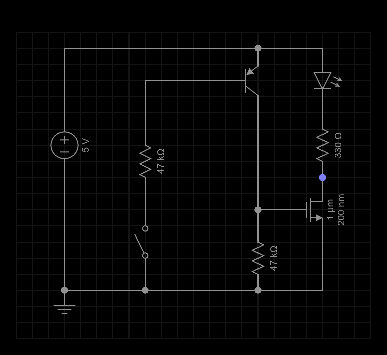
Here is a snapshot of the schematic from Every Circuit (which was handier and a bit cleaner than my usual graph pad + phone camera… even if the N-Channel Mosfet symbol is a bit odd):
The diagram presumes I’ll be using the 5V supply from my existing controller. There is an SPST switch representing the input of the circuit which is the indicator line from the tuner. The output is the drain of the N Channel MOSFET that I’ve shown here connected to an LED via a 330 ohm resistor… but essentially that output will either be open if the input is “open” or “high”, or closed (shorted to ground) if the input is drawing current down from the 5V supply … as if it were “closed” (or trying to be) or “low” if it’s acting like a TTL signal.
Either way, the circuit should clean up the input by slamming the output fully open or closed. Here is the theory:
The input is tied to the base of a PNP transistor through a 47K resistor to limit the base current. The emitter of that transistor is tied to +5V (the positive rail).
If the input represents a high impedance between the positive rail and ground then effectively no current will flow through the base of the PNP transistor and it will be off. This will happen if either the input is something close to +5V like a TTL signal, or if the input is high impedance in general like an open collector would be.
The collector of the PNP transistor drives the gate of an N Channel MOSFET which is otherwise pulled to ground through another 47K resistor. So, if there is no current on the input then there is no current through the PNP transistor and the gate of the MOSFET will be at 0V. This will turn the MOSFET off and so it’s output will be “open” to ground.
On the other hand, if any current (even a fairly small one) flows to ground on the input, then the PNP transistor will switch on and pull up the gate on the MOSFET thus turning it on. The voltage gain of the PNP transistor given a 47K load (the MOSFET gate being essentially invisible to it) will be very high so that even a tiny current through the input will be enough to pull the MOSFET gate well above it’s “ON” voltage.
The choice of a 47K resistor on the input and also on the collector/gate is the same in both cases… it’s a high impedance (but not too high) and a handy value (I have a pretty good inventory of standard values like this). On the collector side of the PNP transistor this means a lot of gain. On the base side of the PNP transistor it means that not much current can flow through the transistor no matter what the input voltage is (within reason). That said, the beta of the PNP transistor is likely on the order of 100 so whatever the input current is at the base the output current will try to be about 100 times that amount.
I measured a 0.8v change between on and off in the existing circuit. The new circuit will amplify that by about the beta of the PNP transistor since the same resistance is on the base and on the collector, so any gain as big as 6 or so will be enough to swing the collector side between the 5V rails. With a beta of 100 I’ll be more concerned about instability than missing a weak signal. (I’ll address that if it shows up; but for now, simpler is better.)
Since I have these parts around I chose a 2N2907 (the complement of the 2N2222) as the PNP transistor; and a 2N7000 (a very common switching part) for the MOSFET.
It was a dark and dismal November, a few years back; and there had been a lot of sudden, unwelcome changes that year. The house was empty, it didn’t feel very festive at all; but I had decided to treat myself to a new IC-705 and some other toys to try and break the gloom.
I sat in my living room pondering all the things, and wondering what to do for an antenna so I could light up the new rig and lighten the mood. I’d had a few discussions with folks who were trapped in apartments or even in tall buildings where there were essentially no good antenna options… so that was fresh in my mind.
I could have used the big loop outside — but it was busy with the robots, and not where I was. I looked out the window into the damp, cold, darkness… sinking slowly into madness.
Then, I thought, I could maybe string some wire around that window and make an antenna… surely I could at least receive with such a thing… and there’s nobody here to stop me or complain about it… My mood got a little brighter… but I knew the math and it wasn’t promising… and strictly receiving didn’t sound like quite as much fun as I hoped for.
I pondered some more, and the outside got darker; but eventually I dragged a few random bits of wire and odds and ends up from the lab along with a few other new toys I had… the random wire and bits and pieces reminded me of what the Grinch had left on the walls when he stole Christmas… it seemed fitting enough.
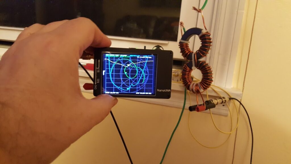
I figured if I was going to have “staring into the abyss” on my schedule I might as well tinker while I was at it… so I also grabbed my new Nano-VNA and my new LCR meter… additional toys I would be acquiring from Santa soon (or well, I could pretend anyway).
I’m normally the sort that draws a zillion pictures and diagrams and does all the math to figure out my designs before I set about building anything. This time, that seemed like a lot of work, and I wasn’t up for it… and since I had new toys that gave me the ability to “see” what the various parts and circuits “looked like” electrically, I decided to go the other route and just try stuff and see what happened. I figured I’d eventually end up with “something”, or I’d keep playing with it to see what I could learn. Besides, I’ve got plenty of theory in my head to give me some direction… it would keep me busy anyway.
The first idea I had was to take some shielded, multi-core cable I had and cross wire it so that it would be a 7 turn loop the size of my front window. I figured that with a large diameter and 7 turns it would be a pretty good inductor. I also thought that with the shielding in place it would be purely magnetic and so probably less noisy. But, in my temporary excitement I forgot about the inter-electrode capacitance. Each of those wires were all right next to each other inside the loop shield so that would defeat the multiple turns. I figured this out after trying it and being disappointed with the results.
The multi-turn loop idea had a few fairly narrow resonant points, but it didn’t really act like I wanted it to and was going to be really fiddly with the tuning. In fact, I had a devil of a time getting it to be sufficient at any of the frequencies I wanted to use.
Once I realized that the multi-core idea wasn’t going to work I grabbed some electrical ground wire I had laying around and decided to try a single loop with a loading coil to make up the difference in electrical length. That was less chaotic, but also didn’t quite work.
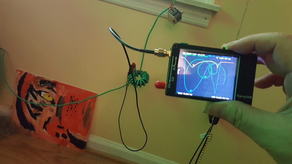
I knew I didn’t want to use a coupling loop because that would be impossible to hide as an inside antenna around a window… and well, also because I just didn’t like the idea! But that did make me think about the fact that that’s really a kind of transformer… So, I wrapped a couple of turns around the loading coil I’d made and that seemed to work much better.
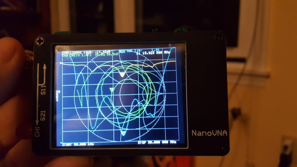
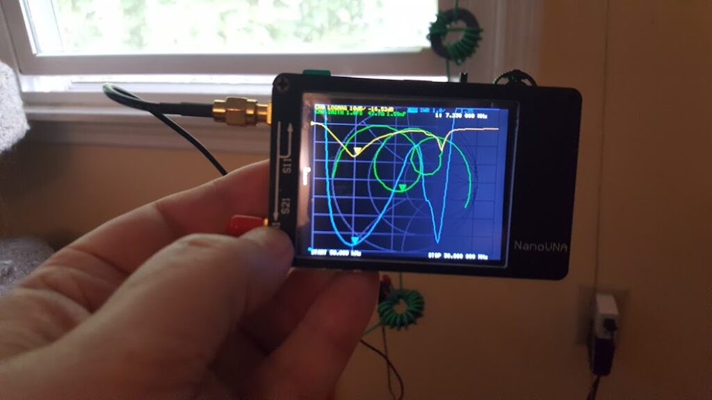
I tried a handful of variations on that theme and got similar but varying results. I could see what was happening using the Nano-Vna, and I could measure the inductance and capacitance of the parts I was using with my LCR meter. This gave me a few ways to turn the wheels in my head… and so I kept tinkering… and it became morning, and then evening again…
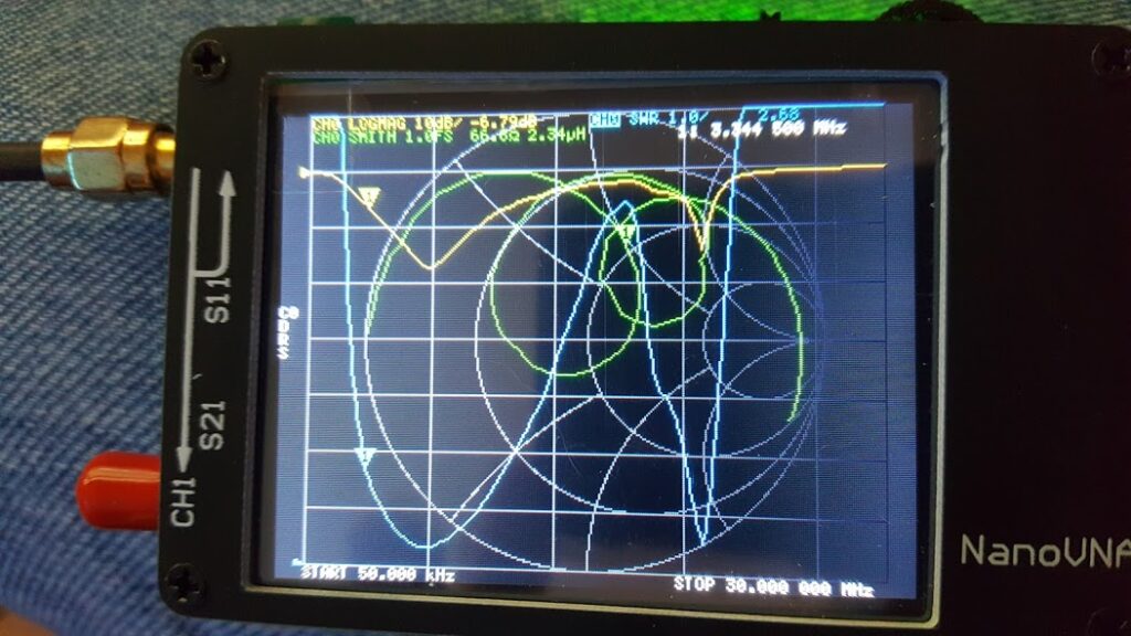
2 turns on the primary of the transformer and 14 on the secondary with the tuning capacitor in series seemed to get an interesting result; so I played with that for a while… but I realized that the capacitor wasn’t really helping that much, and I also couldn’t get that second resonant point to be where I could really make use of it.
I started experimenting again… and essentially replaced the capacitor with an inductor… a loading coil, just to see how that would change things…
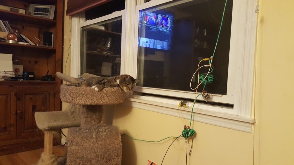
Tiger was supervising all of this work… Truth be told, it was Tiger who suggested replacing the cap with a coil and I told him it was a crazy idea and that it would never work because that’s not how you tune loops and … well, he’s a cat and … just … oh FINE, FINE! I’ll put in a coil and show you how it doesn’t work like that … you’ll see right!?
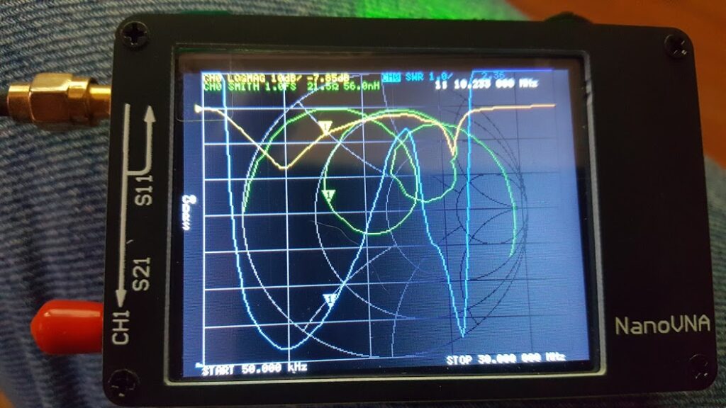
Nope, the crazy idea actually worked… the second resonant peek disappeared and the first one expanded… not quite as much as I had wanted, but quite a bit. Tiger, just looked at me as if to say “I told you so…”, but being a very cool cat, he refrained and just let me soak in the moment… then went back to doing cat things and occasionally supervising my continued tinkering.
After stumbling upon this solution I thought about it and realized I’d created a match that draws on several techniques.
The loading coil is borrowed from short whip antennas where it makes them electrically longer and therefore (typically) a higher impedance that’s easier to match to the feed line.
The high ratio transformer is borrowed from end-fed dipoles and similar kinds of antennas where it converts the high impedance at the end of the wire into a lower impedance that matches the feed line.
The loop antenna fed this way is completely balanced so it doesn’t need any kind of counterpoise nor does it have any free ends of it’s own which might expose high voltages.
I decided to take this to an extreme of sorts and scale it up. I basically doubled the number of turns on the loading coil and ramped up both sides of the transformer as well. The primary now had 3 turns, and the secondary had 30. The loading coil has 16 turns symmetrically split and bound to the secondary of the transformer so that there are no cuts in those wires… that is, the secondary of the transformer becomes the loading coil on a second core.
I have since called this contraption a Swamped Impedance Match because conceptually, the antenna and loading coil virtually guarantee a high impedance that “swamps out” the vagaries of the radiating element; and then that high impedance is divided by 100 using the high ratio transformer so that any of those “vagaries” are also divided by 100 thus making a reasonable match to the feed line across a wide range of frequencies.
The results were pretty good as far as matching goes. The antenna with the match manages to have a very wide frequency response covering most of the HF bands I wanted to play with and offering a usable SWR from about 4 MHz up to about 20 MHz. The antenna wire itself is a square about 80 inches on a side… but the actual loop isn’t critical. I picked that just because it would perfectly fit my window all the way down to the floor… the idea being that with any kind of drapes on the window the antenna could be completely hidden from view!
BUT, I hear you say; and I said it too; just because the thing has a reasonable 50 ohm match doesn’t mean it makes a good antenna… even if you can receive with it that doesn’t mean it’s actually a “good” antenna. It could be just a mediocre, and somewhat frequency specific, dummy load!
Tiger scoffed, and gave me a look, and an up-nod, and said (via kitty mind control) “You’re the Mad Scientist … do some science and prove it to yourself.”
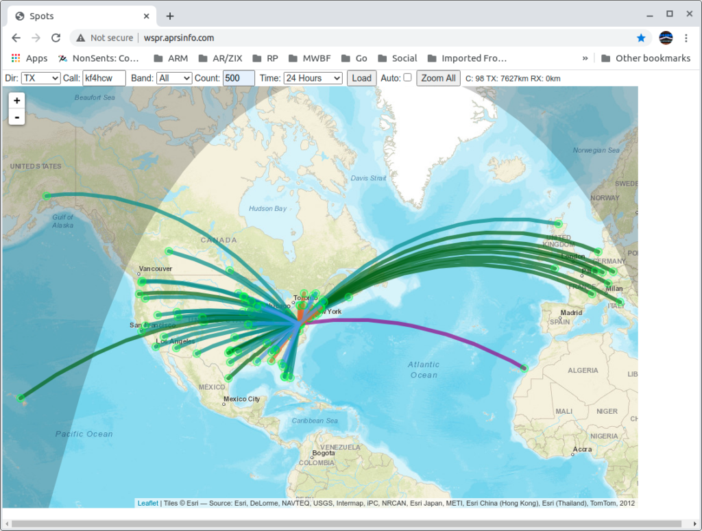
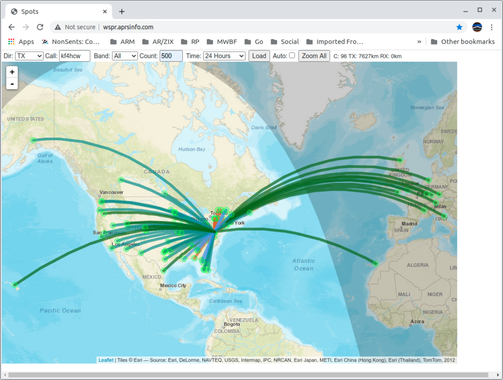
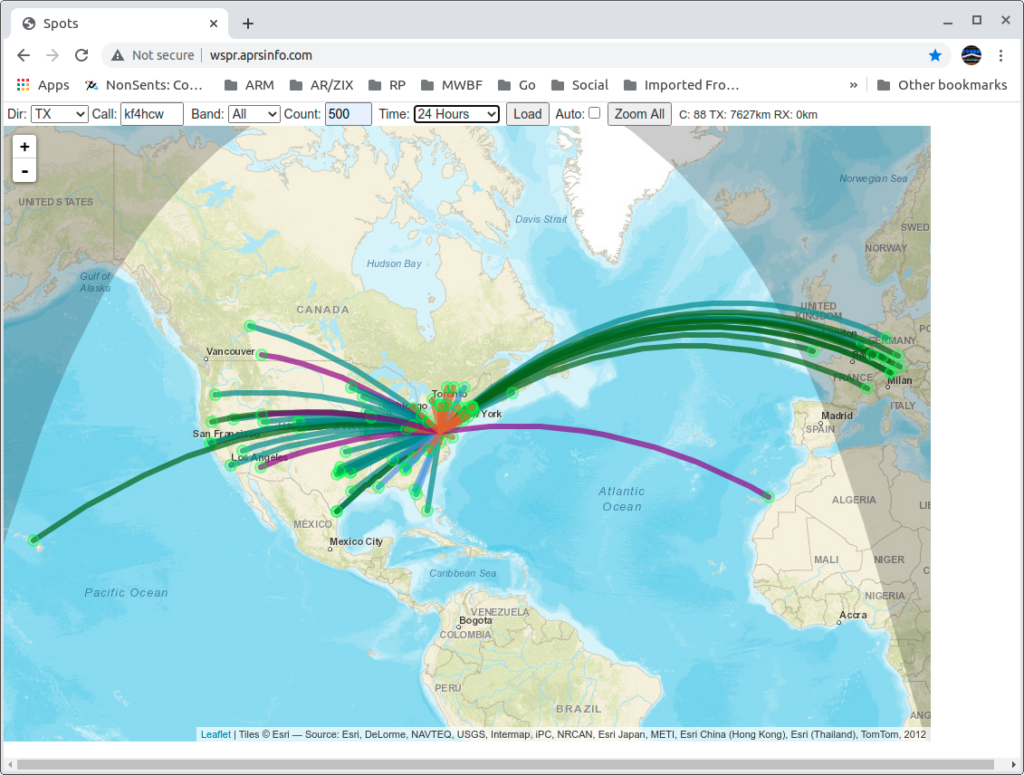
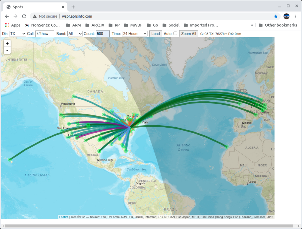
So, I turned off the big rig temporarily and fired up WSPR on my Spectre laptop running Linux, and my new IC-705; connected it to the Terrible Tiny Antenna; and let it run for a couple of days to see what the rest of the world could tell me about the antenna’s performance.
It worked! No, really!! WSPR data from this setup shows fairly respectable results even when compared to my big loop in the back yard!
Here you can download the raw data (a text file) from that experiment. The top part of the data is for the Terrible Tiny Loop with the Swamped Impedance Match; and the bottom of the file is data from the big loop (with an SG-237 tuner at it’s feed point) for comparison. Both were running 5 watts. The small rig in my living room with the IC-705, and (at separate times) the big loop running from my lab with the Flex 6300.
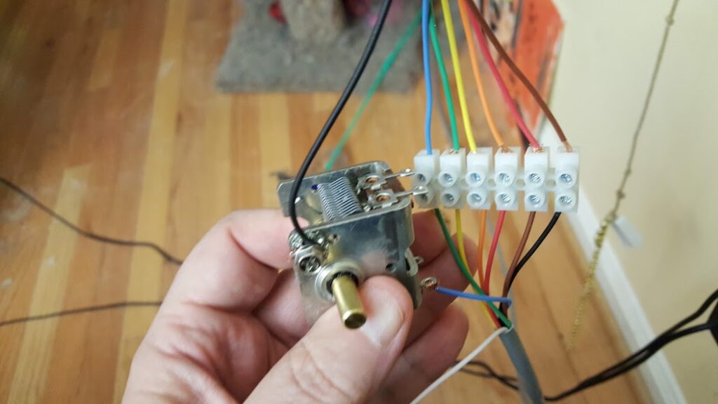
Just to be extra sure about the results I asked some friends of mine in AMRAD to build the antenna themselves … and they also found it worked pretty well (though, their build quality was a bit better than my initial experiments.)
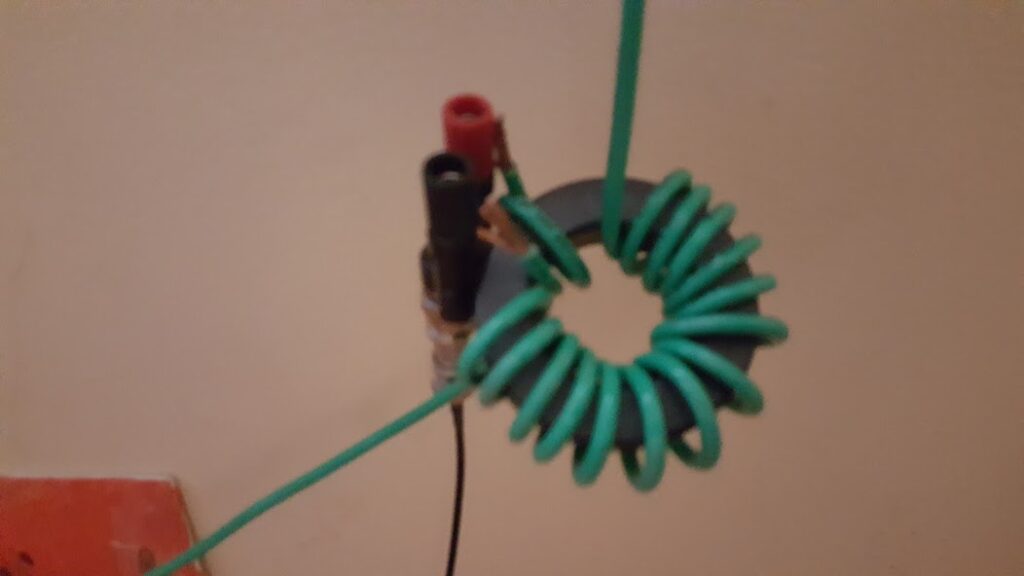
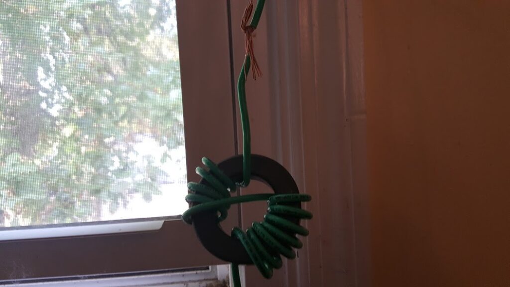
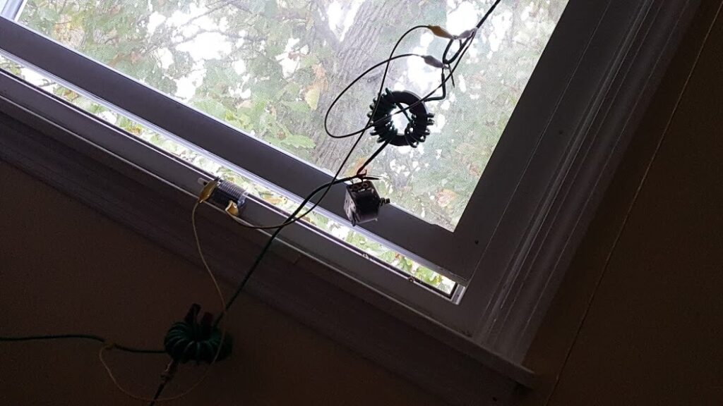
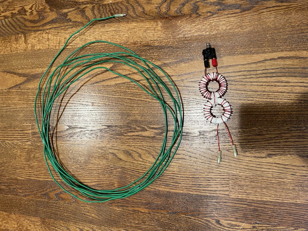
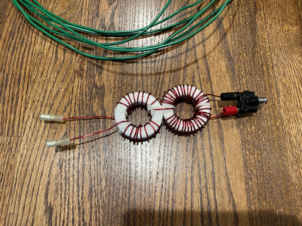
Here are some pictures of one of those builds:
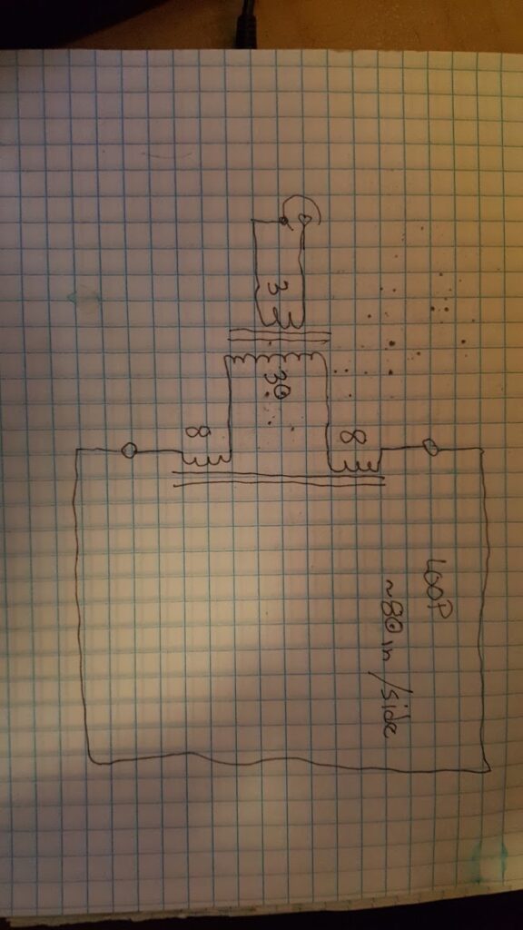
Here is a schematic I hastily drew up for my friends to use as a guide… it’s simple enough as is the construction of the antenna and match.
The toroids are typical of what you might use for an HF balun (FT-240-43). Begin with about 4 meters of wire folded in half and wind the secondary on the first core from that mid-point. Half of the windings on each side of the core spaced so that they finish just opposite of the starting point.
Then, use a zip tie to attach the second core where the secondary wires are free and wind each of those wires through the second core about 8 turns on each side as if they are one winding split in the middle at the transformer.
This completes the secondary of the transformer and the loading coil with a single piece of wire. There should be just a bit left so that you can make some kind of connections for your antenna loop. Banana jacks are a good choice here.
Then complete the primary of the transformer by winding 3 interleaved turns of wire at the point where you began the secondary. Attach the free ends of the primary to some kind of coax connector of your choice. (it might be helpful to put a small value capacitor across the primary, but it’s not strictly necessary.)
The Swamped Impedance Match can be left loose like this for experiments, or it can be put in a box if you want it to look better and hide under your window behind your curtains 😉
The antenna loop itself as originally designed is approximately 80 inches on a side, but given the nature of the antenna the length is not critical and as long as you don’t have a lot of metal in your walls you can probably mount the antenna anywhere that works for your needs. I have taken this antenna out for demonstrations and simply stood it up in the air on a pair of lighting tripods with good results… it’s appears to be very tolerant of variations on installation and environment.
While the large toroids I used might imply that you can use some significant power with this — I don’t recommend it… certainly not if you’re using it inside where radiation and interference with other devices might be a concern. I simply used those toroids because they were what I had on hand. I suspect you could easily reduce the size and cost of your toroids and still get good results. Let me know if you try this and how it goes with any of your experiments.