I wanted an antenna that would be good for all HF bands; that would have reasonably good performance characteristics; and would be reasonably stealthy. Clearly, a wire antenna of some type… but what type?
There are dipoles that would work, and I’ve used them in the past, but they pose a couple of problems– mostly stemming from the heavy feed line and balun hanging in the middle, and the limited options for hanging a multi-band dipole on my property.
Then I looked at an inverted L… but that would need a counterpoise, and probably a complex one at that. Then it occured to me that if I connected the counterpoise to the far end of the inverted L I would actually have a large vertical loop – and that might even perform better! So that’s what I built.
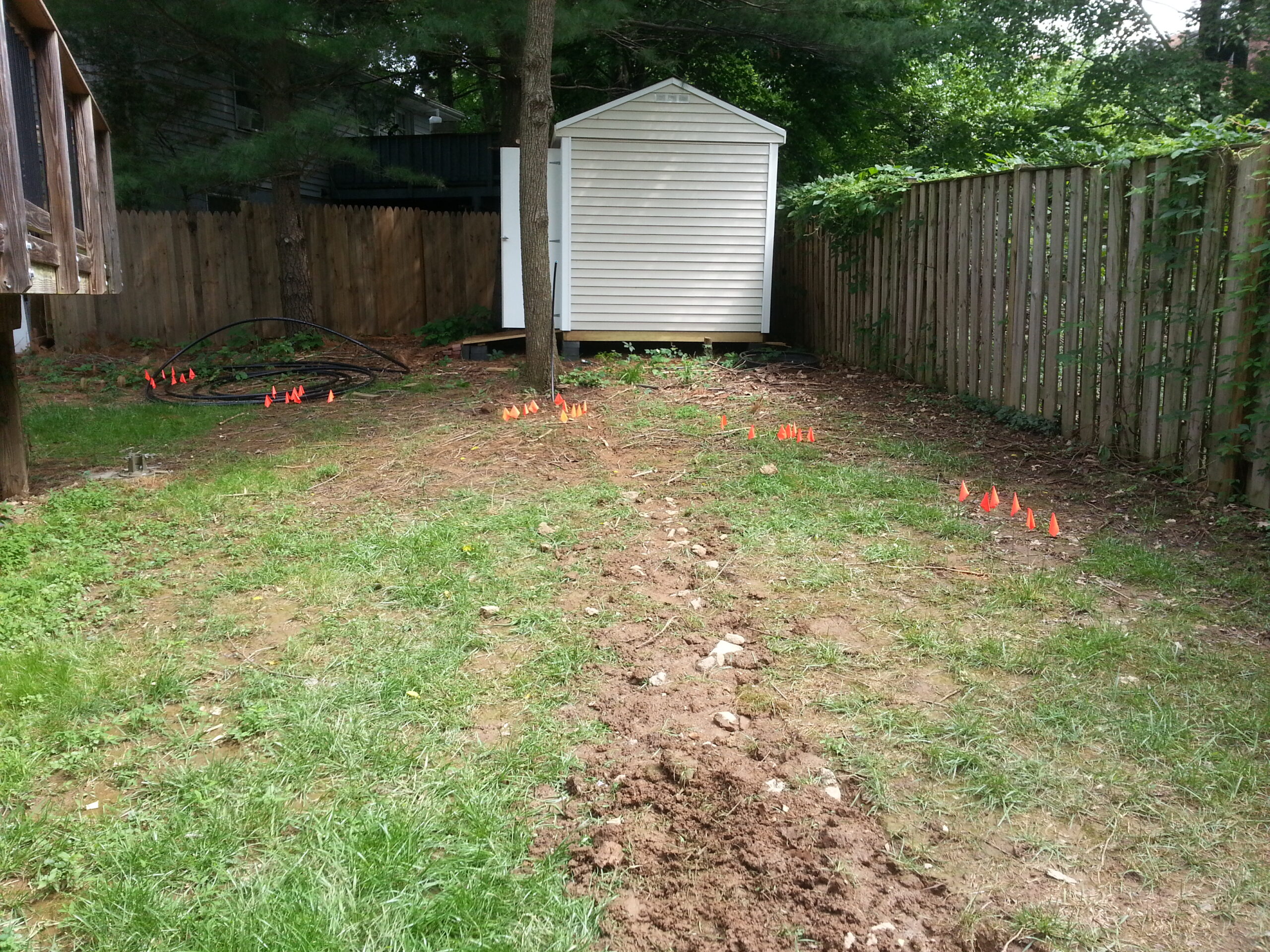
I had a few other constraints to deal with though. For one thing, kids play in my yard (often without my knowledge or permission), so I would have to make sure that the antenna stayed safe for anyone around it and that all of the low, reachable elements were covered. I also wanted to have the tuner at the feed point in order to have minimal losses in the feed line.
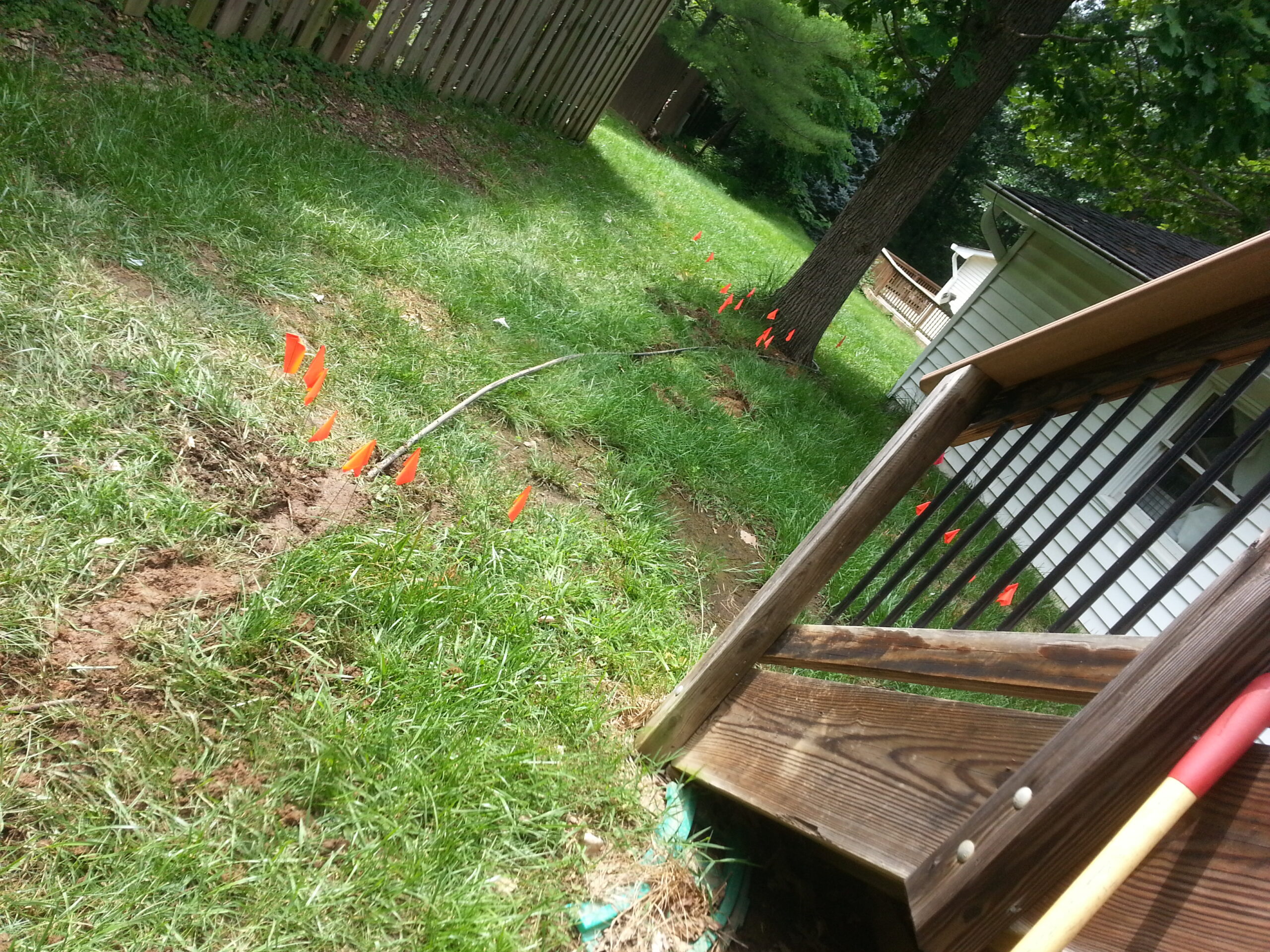
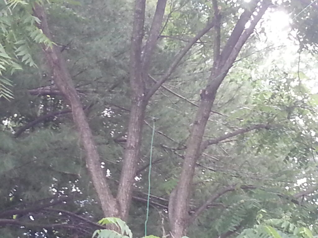
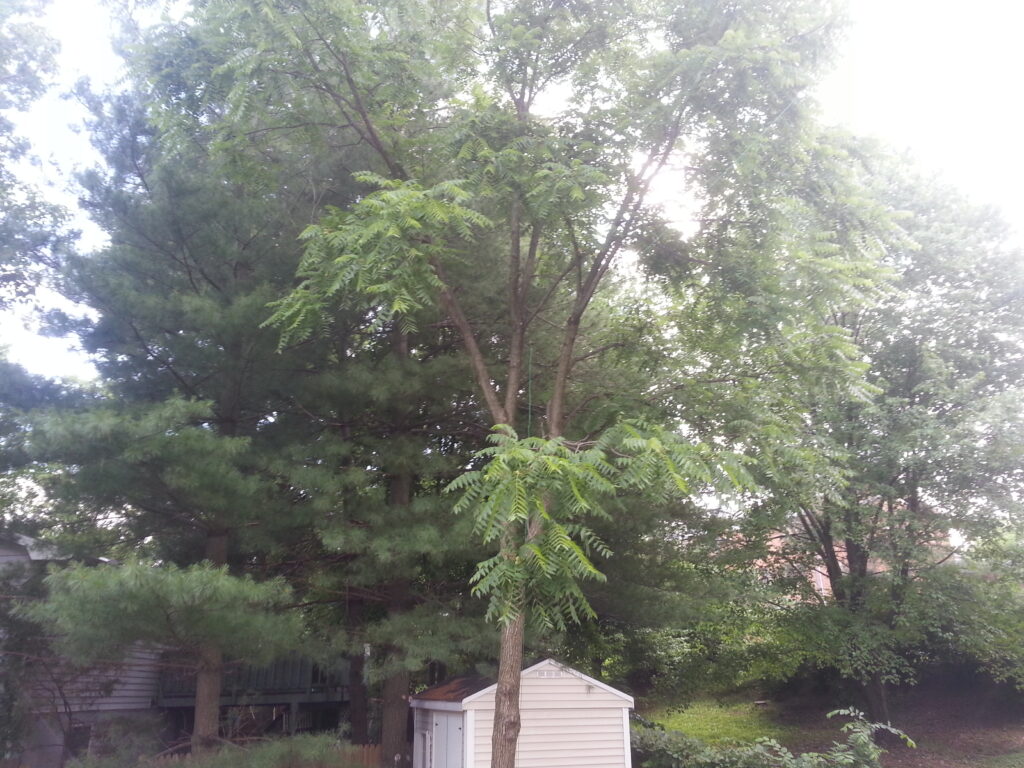
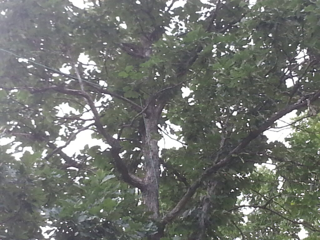
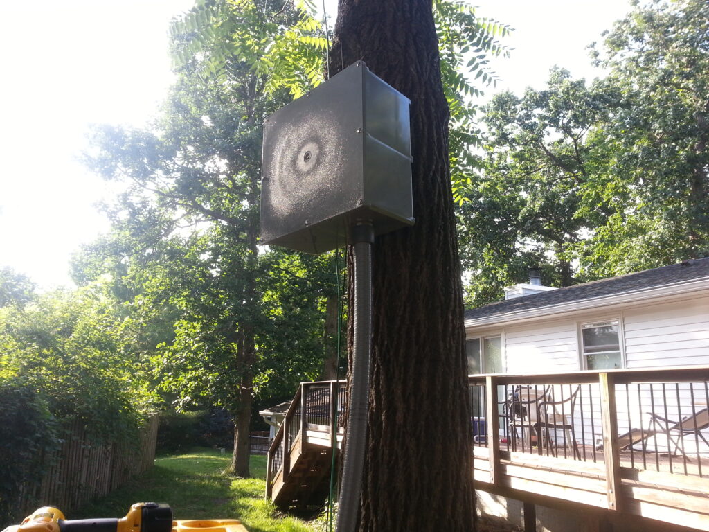
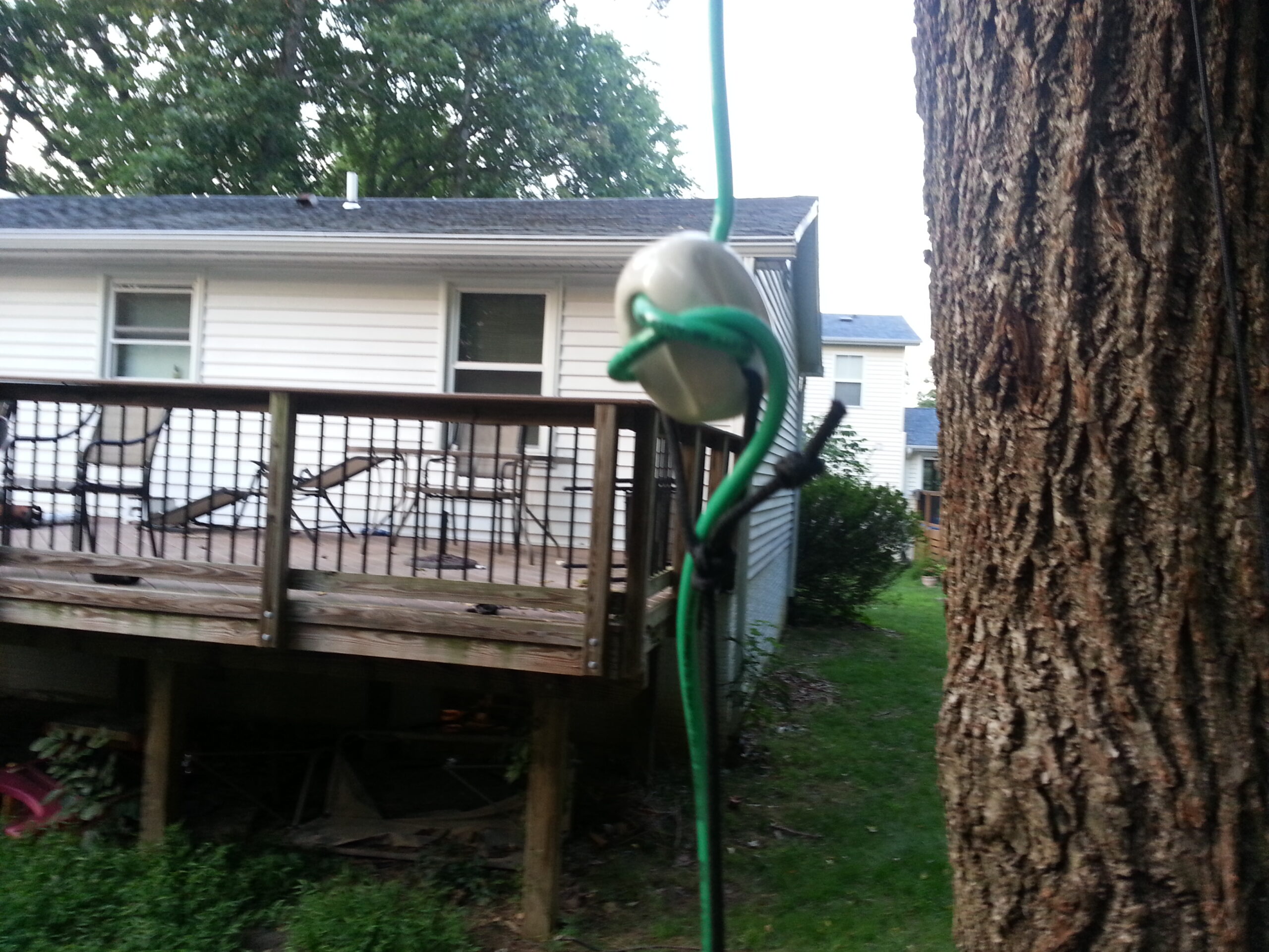
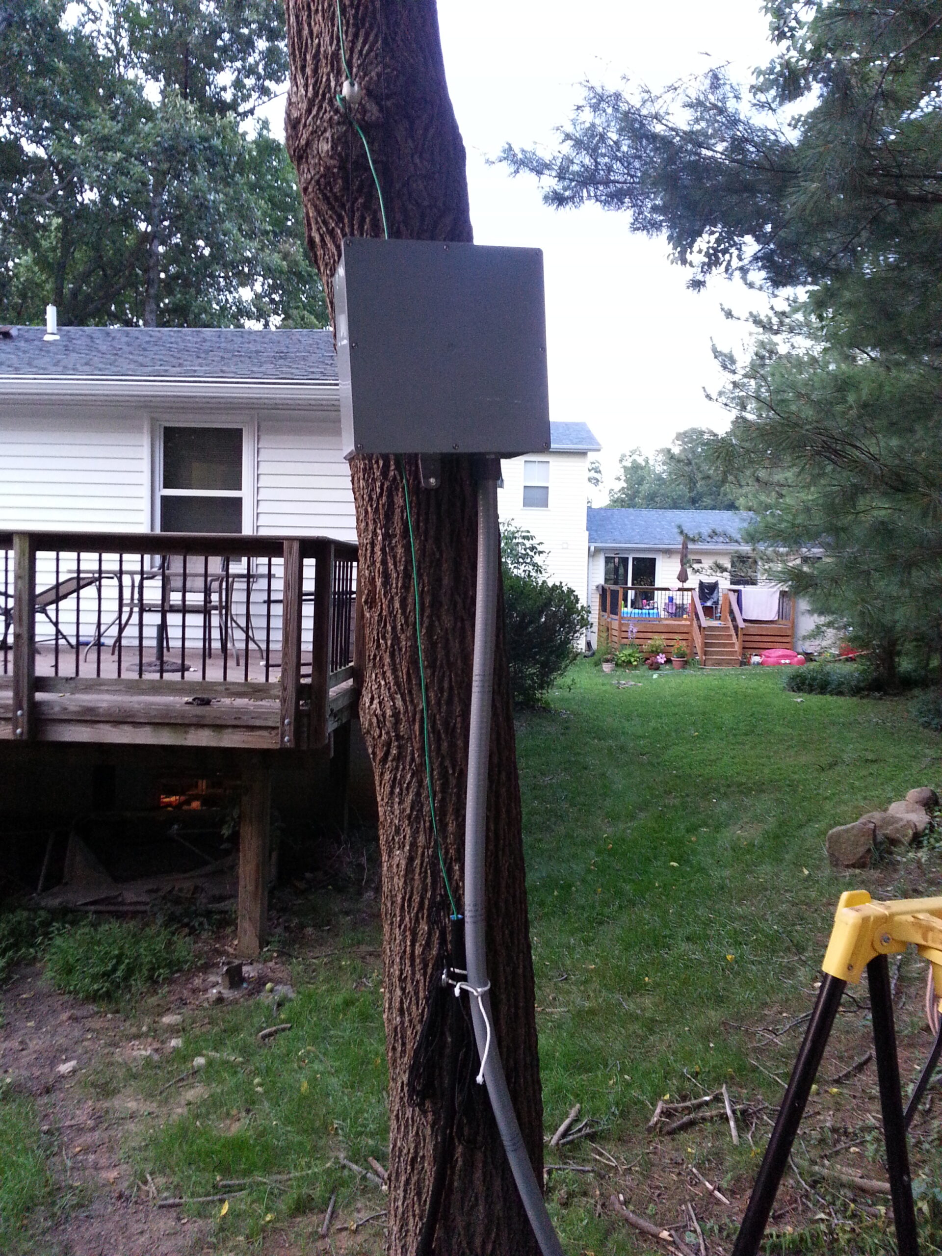
The final design would have the vertical sides of the loop going up some trees about 65 feet apart; the bottom of the antenna buried a few inches under ground; and the tuner up about 10 feet in a box to protect it from the weather as well as any uninvited fingers. The wire itself would be insulated, and parts of it would be in conduit to protect it from the weather, squirrels, and other hazards.
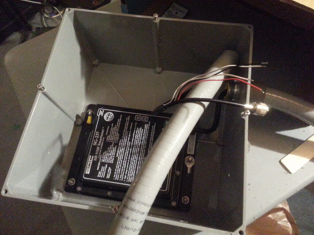
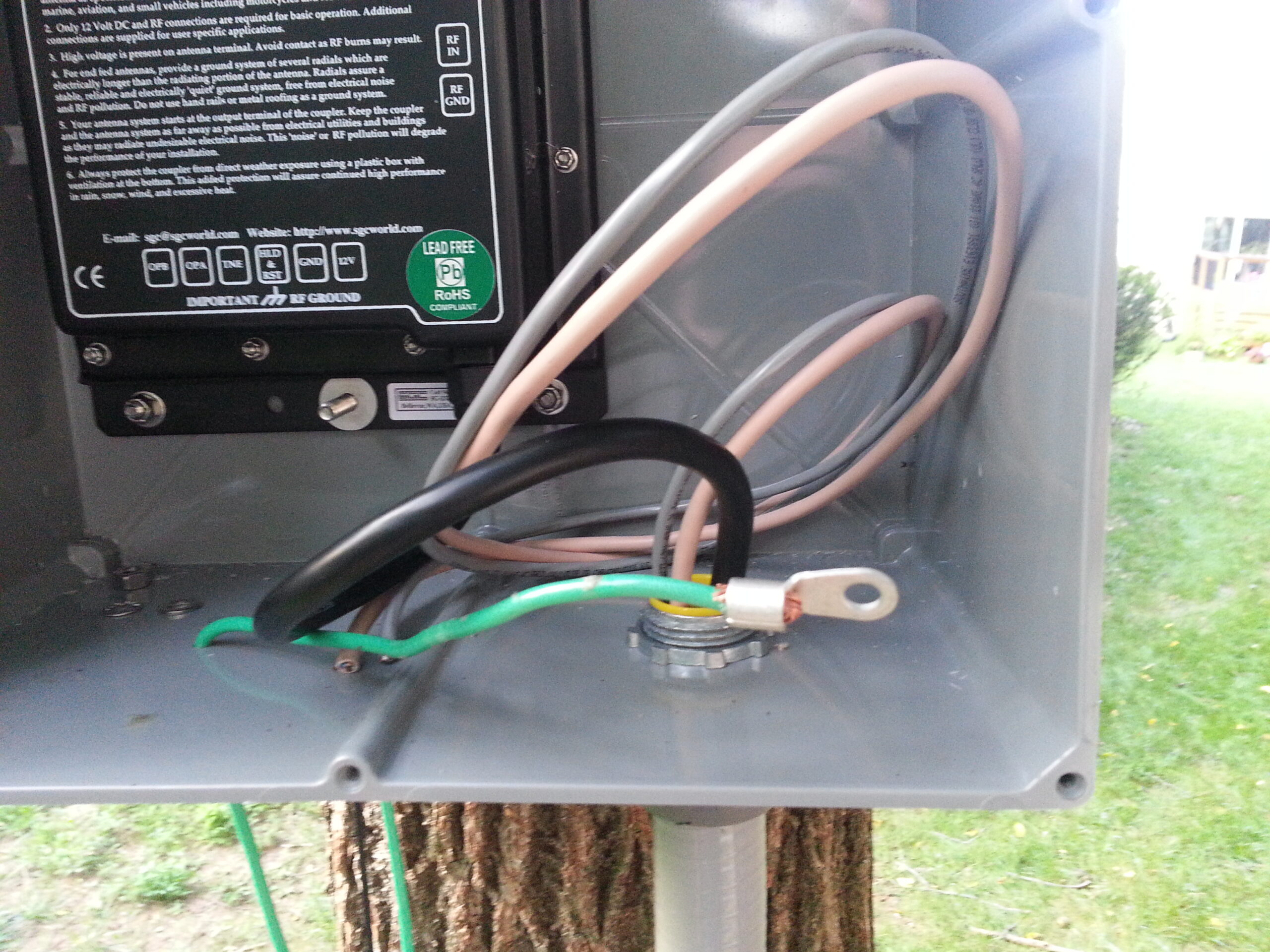
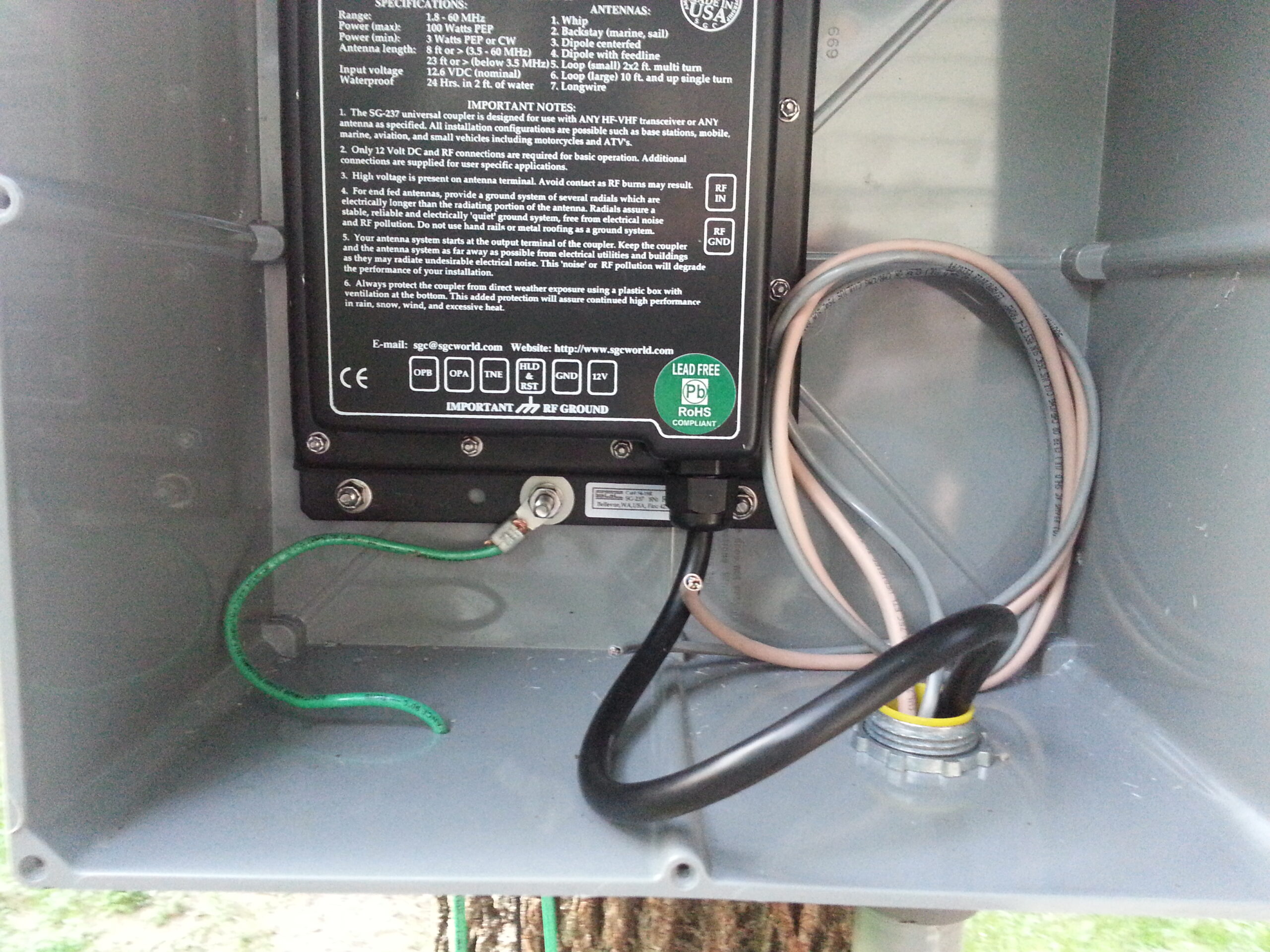
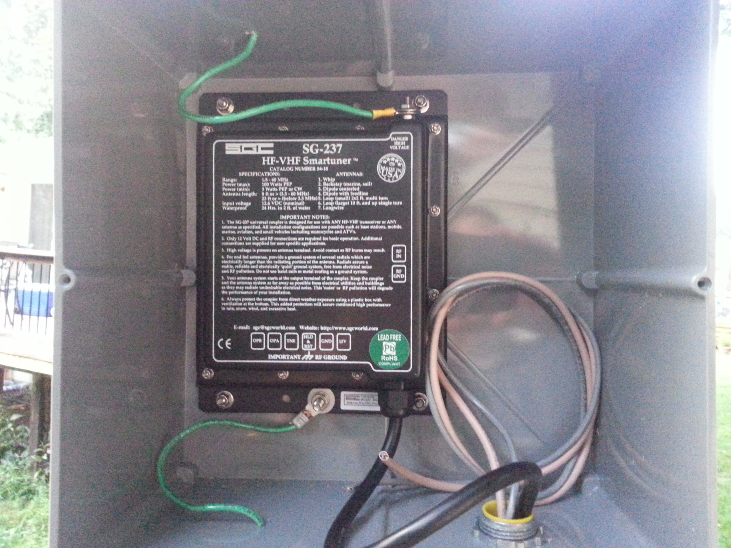
The tuner itself is designed to be out in the weather, but by putting it in a box the termination points are hidden away, the tuner is further protected from the elements, and I have the option to eventually put additional equipment in the box.
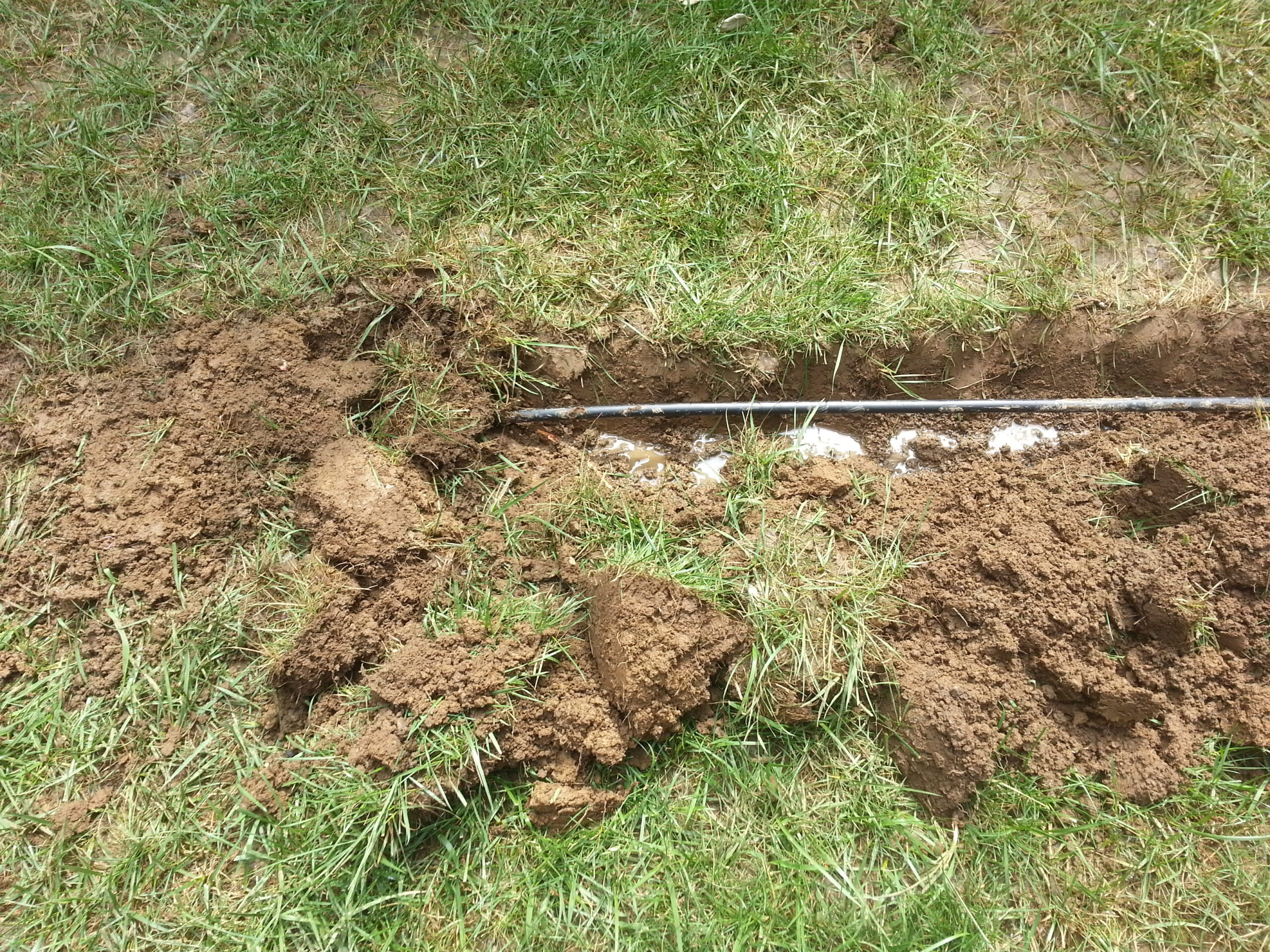
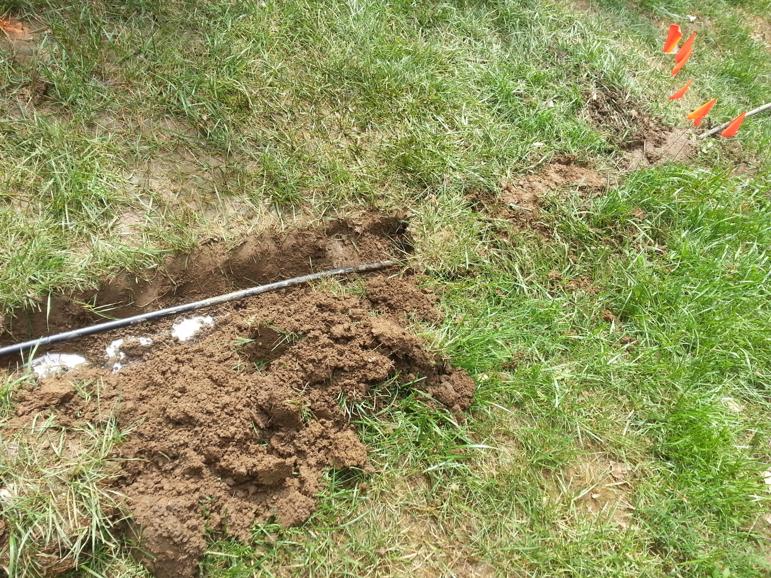
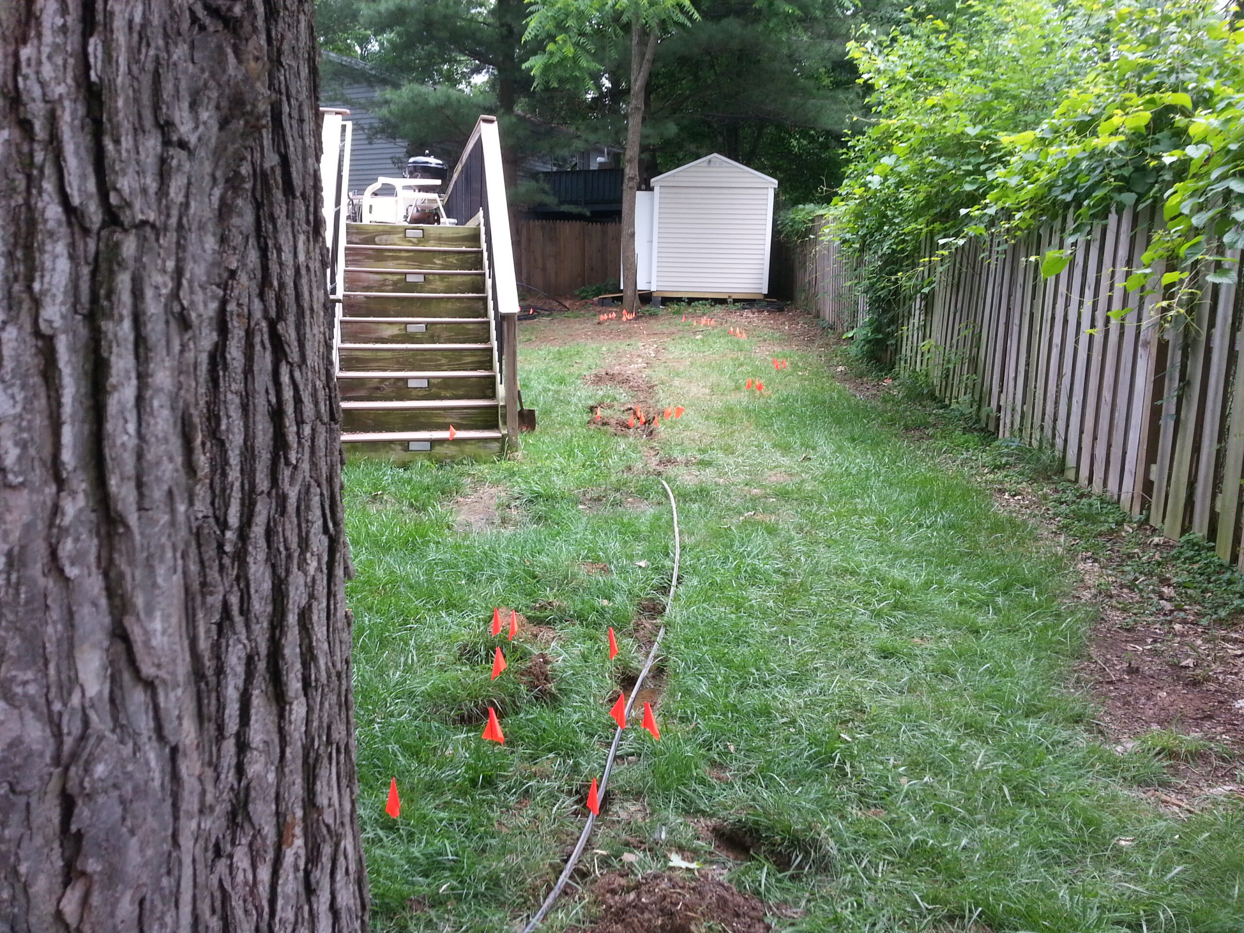
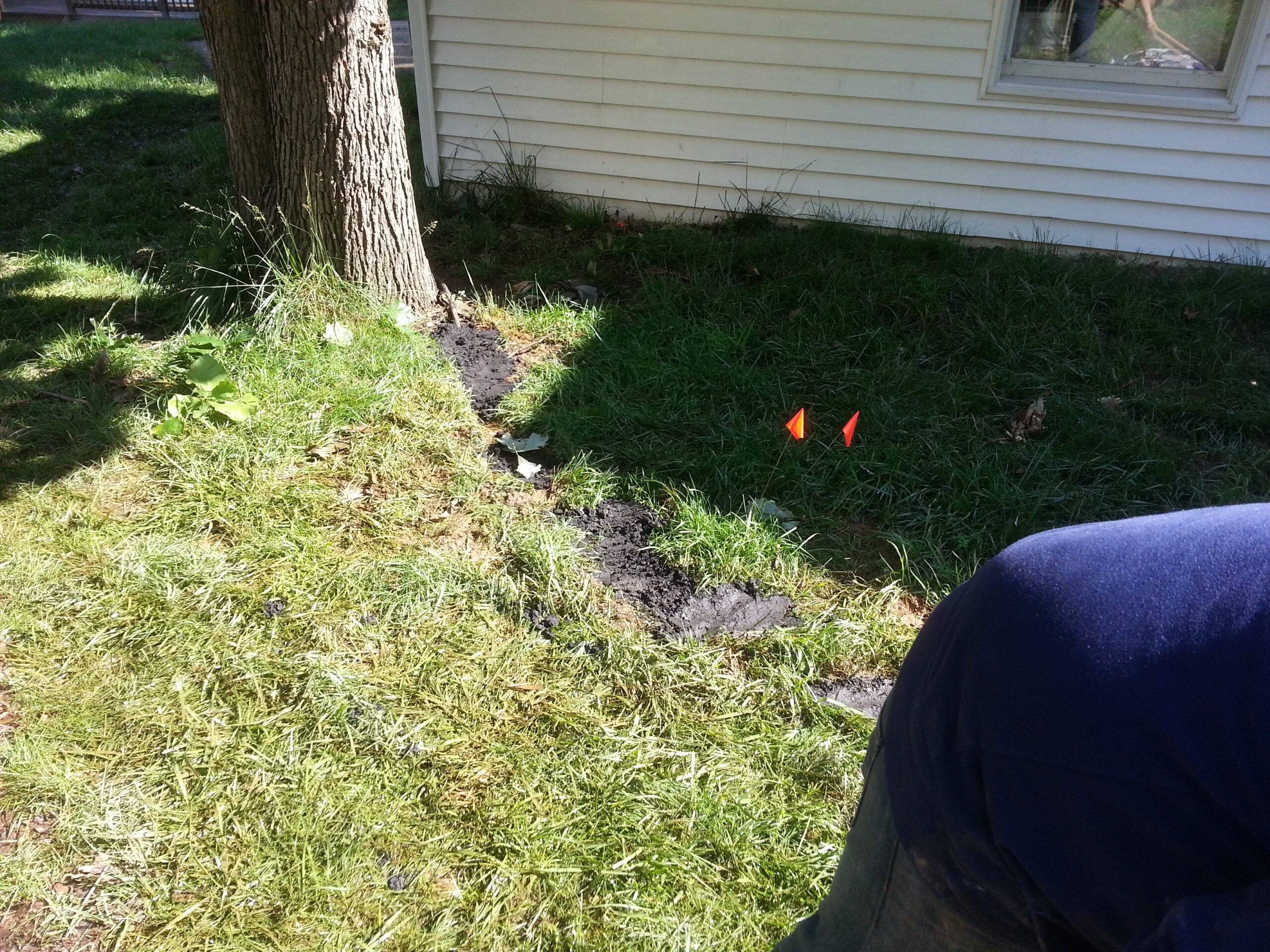
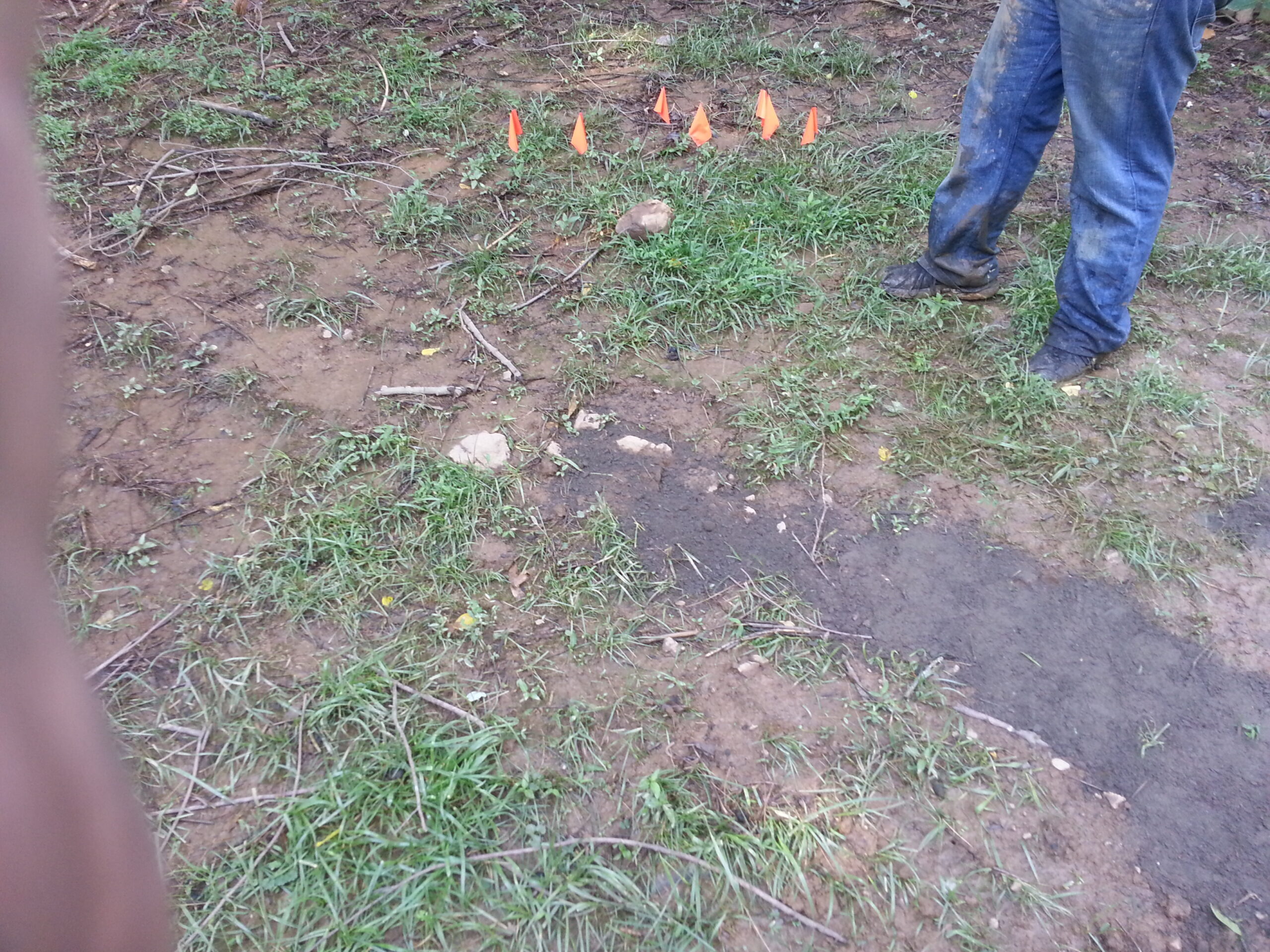
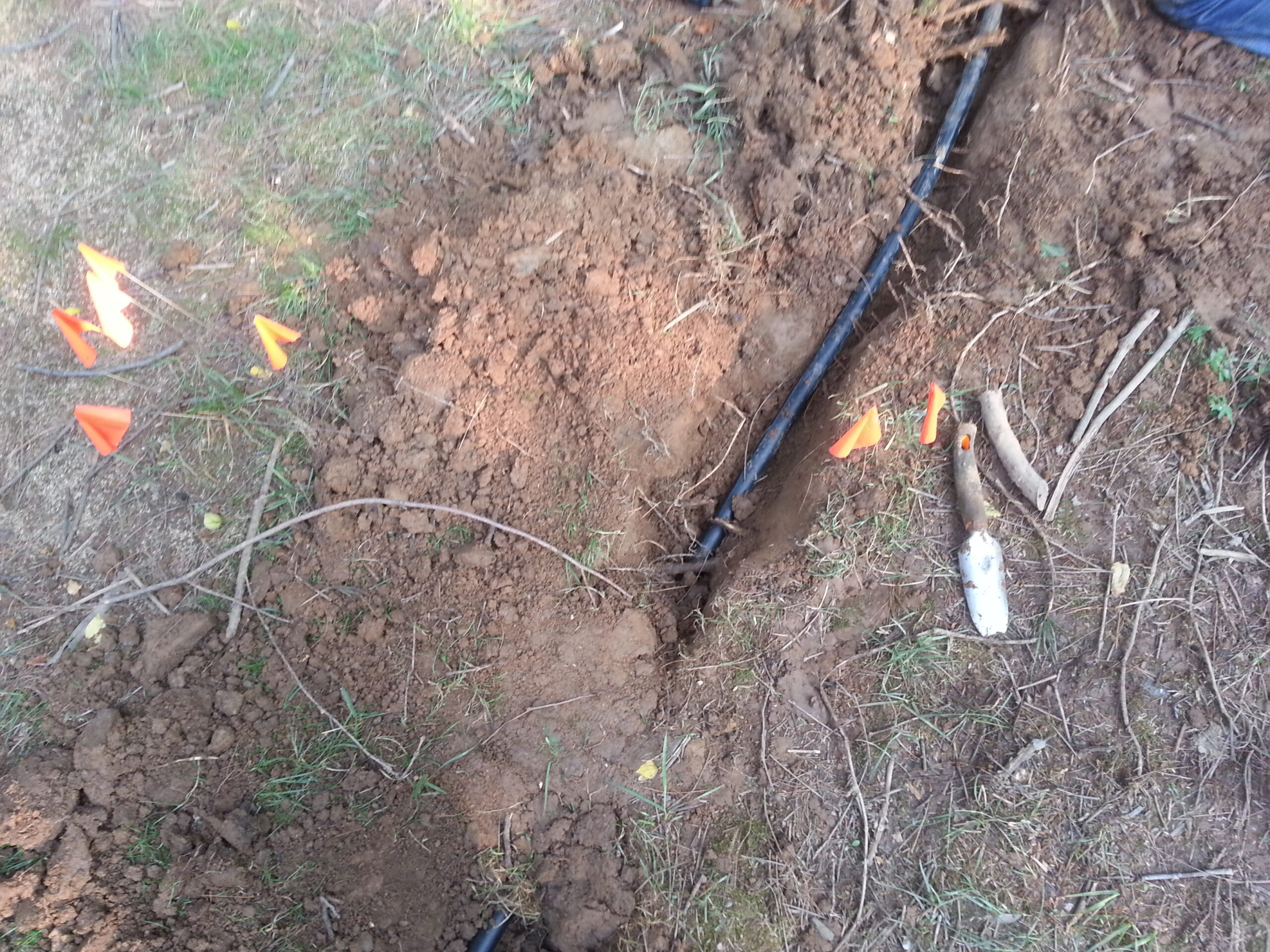
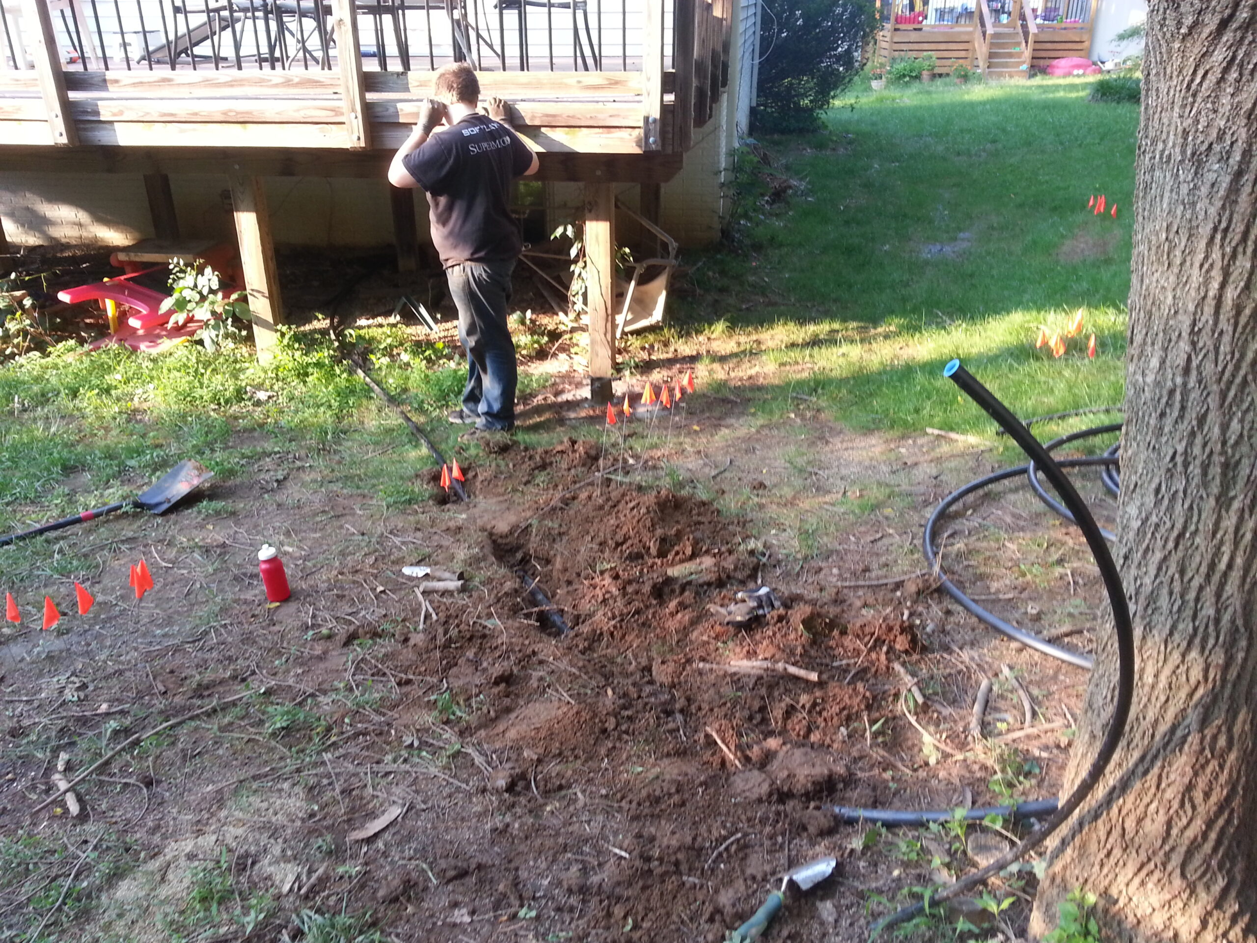
The first step was to call Miss Utility and get the yard plotted so I could avoid my fiber and other possible hazards. Then we could begin burying the conduit. I say conduit, but really, it’s cheaper than that! I opted to use lawn sprinkler tubing which comes in various diameters, is designed to survive under ground, and is easy to work with.
The smaller diameter tube would go between the trees and be just big enough to carry the bottom part of the antenna. A larger diameter tube would go between my lab (in the basement) and the closest tree in order to carry the feed line and various other cables.
The next step was to assemble the loop and get it ready for installation. I would hire a “tree guy” to climb the two trees and install the hardware… but before that could happen I would have to have all of the ground work complete and ready to go.
Now, as a side note, my usual methodology is to do all of the math and drawings in meticulous detail and then execute that plan. This was no different. I had spent hours figuring out precisely what size loop would be required to have the least conflict on multiple bands and give the best performance overall. Everything would be precisely measured ahead of time so the installation would go off without a hitch and the end result would be perfection. You can probably tell by now that’s not how things worked out right?!! Indeed this experience broke me out of my shell and started me down a path of engineering both by intuition and by design somewhat abandoning my tight grasp of all things mathematical in favor of a more holistic approach— more on that later.
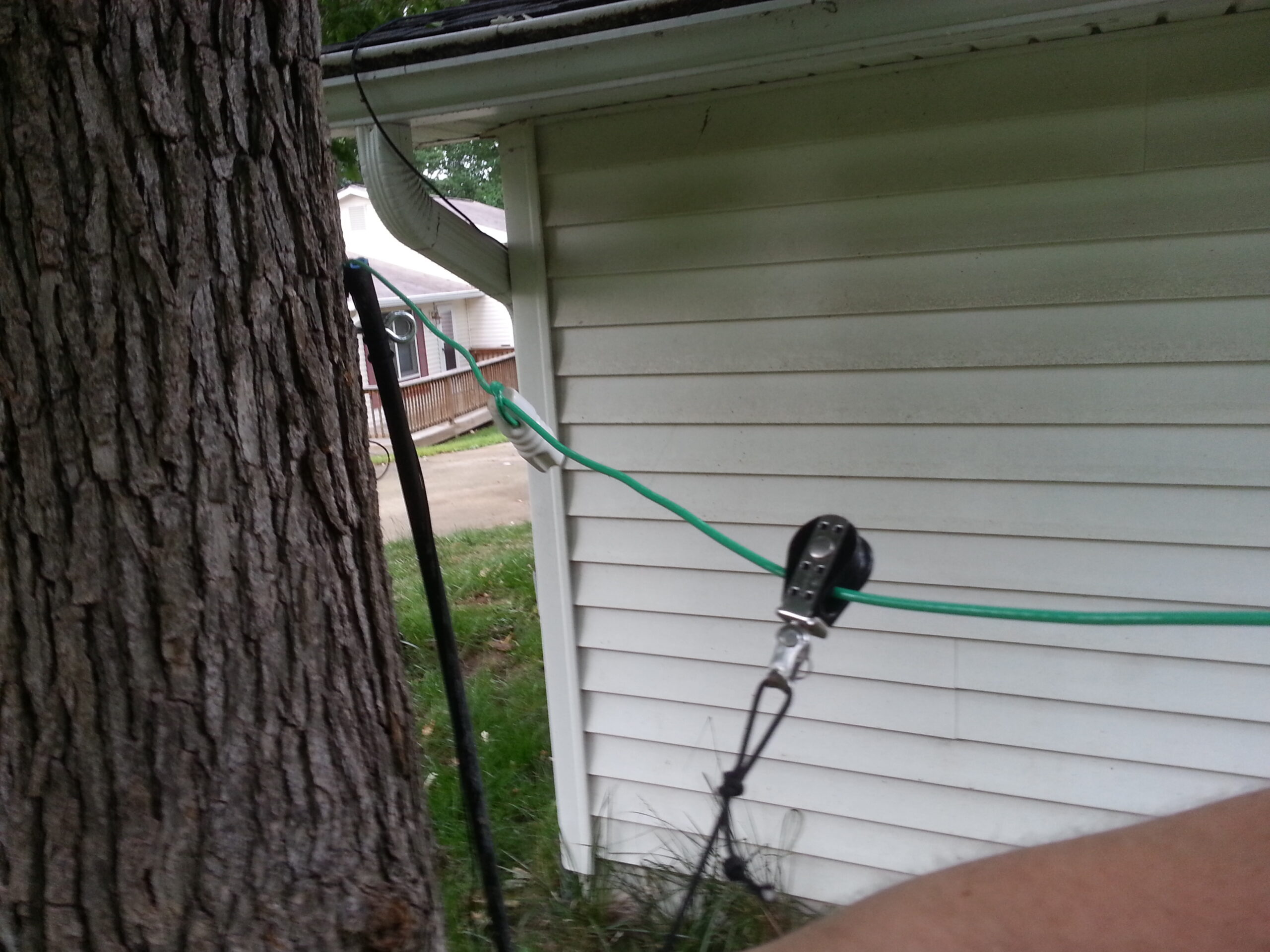
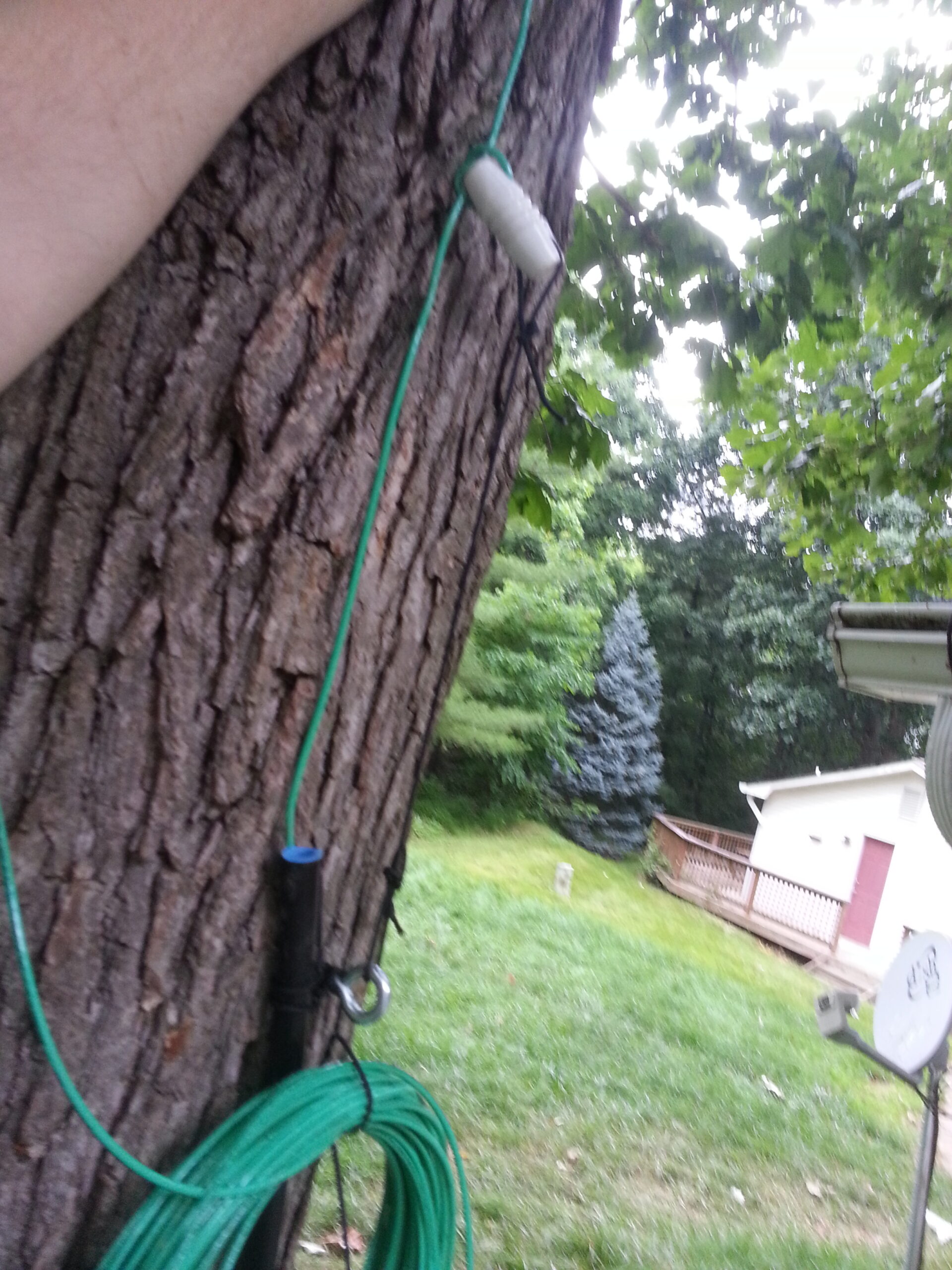
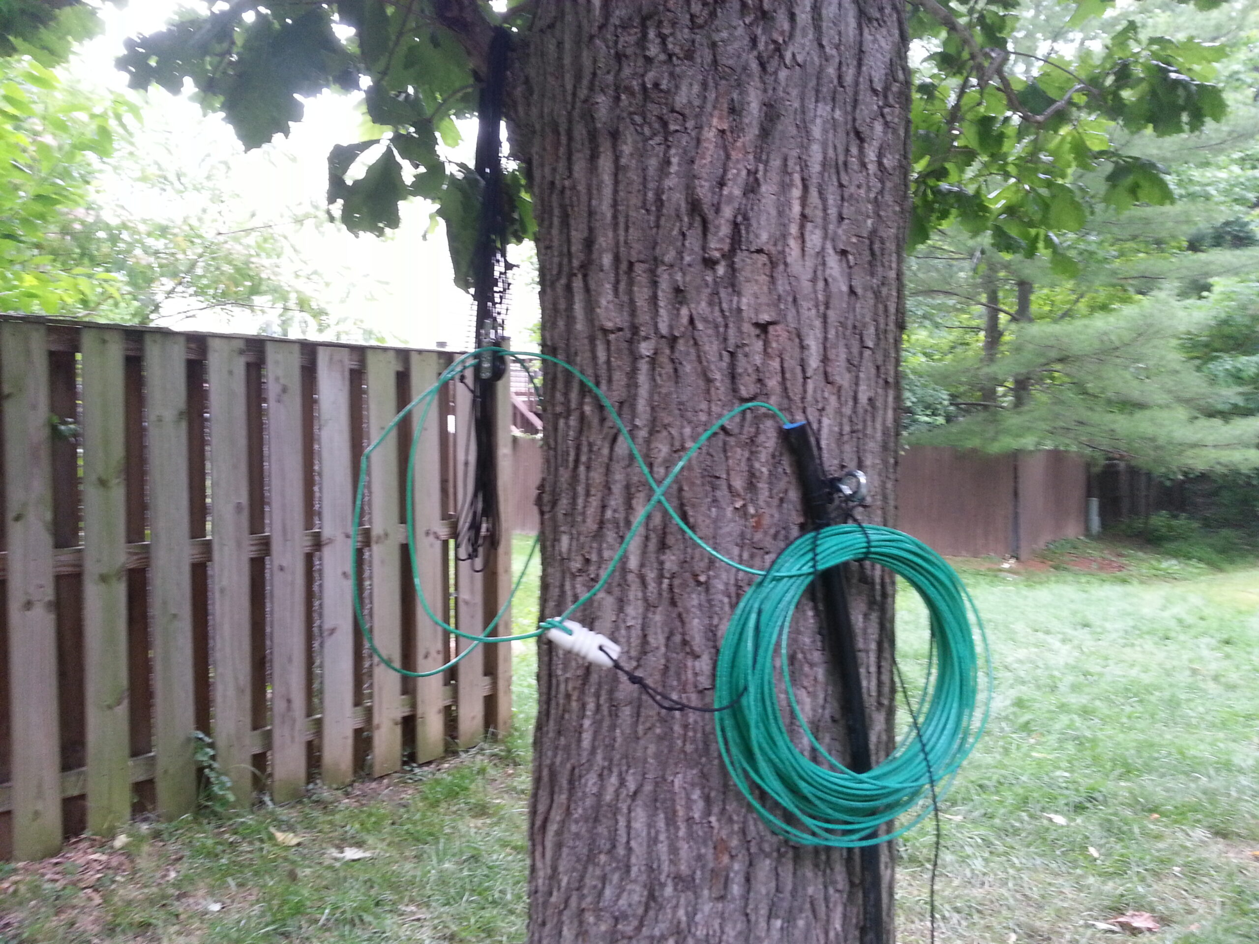
With the conduits in place the antenna wire, made from common electrical wiring, would need to be pushed through the conduit and various hardware installed. This included pulleys for each end to allow the antenna wire to move freely in the wind; and some insulators as strain reliefs in strategic locations to keep the wire from moving “too freely.”
The first excursion away from my usual engineering practice was how I treated the installation of the insulators. I had in mind to avoid joints and to keep the original insulation in place as much as possible. So, instead of a complicated arrangement at insulator locations I decided to simply push the wire through and tie a simple knot. In theory this tiny additional inductance would be invisible — and if that turned out not to be the case then I could always strip the insulation later and solder the joints at the insulators. As it turns out, my assumption about the inductance was correct and I never needed to rework the insulators.
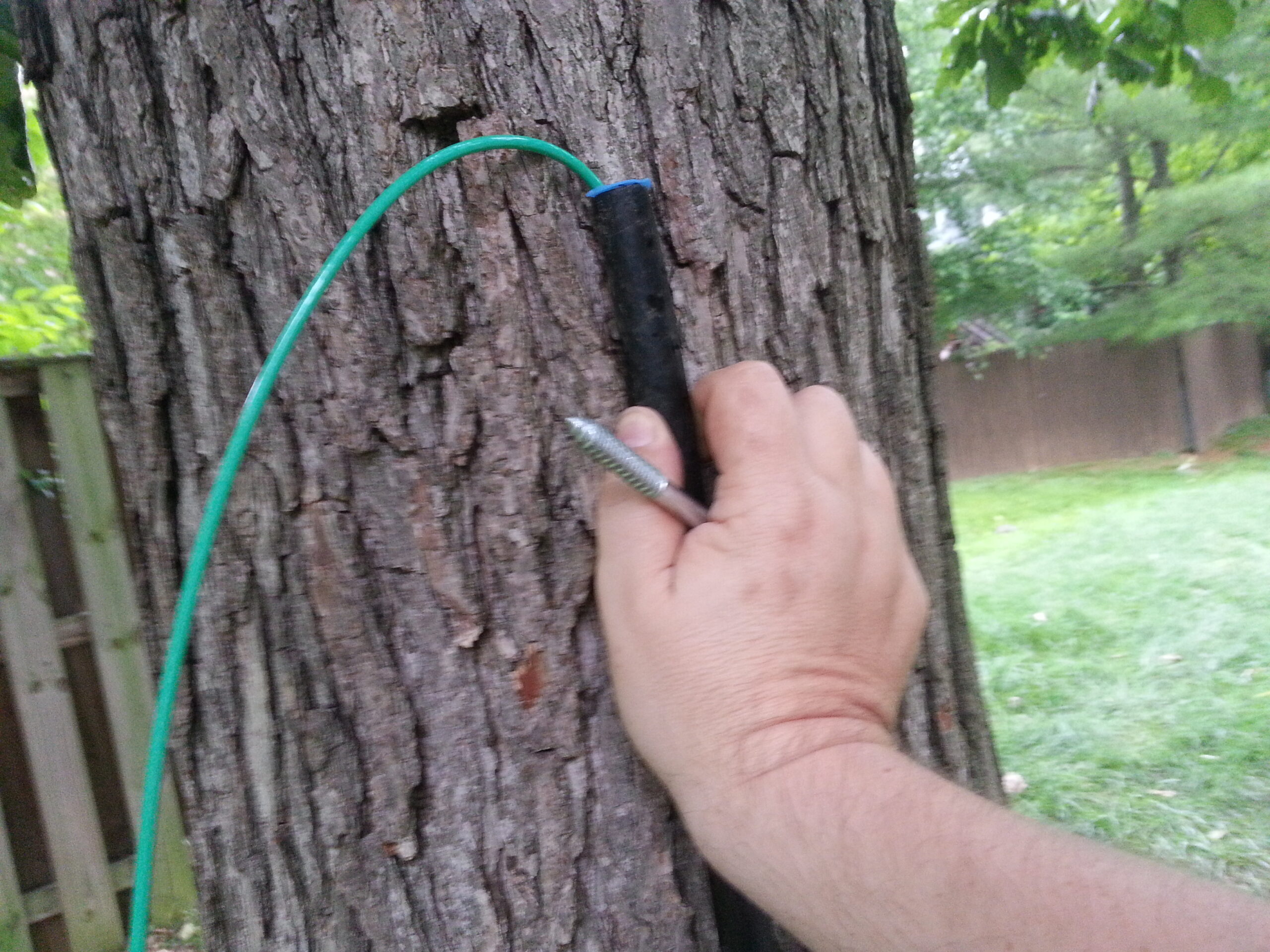
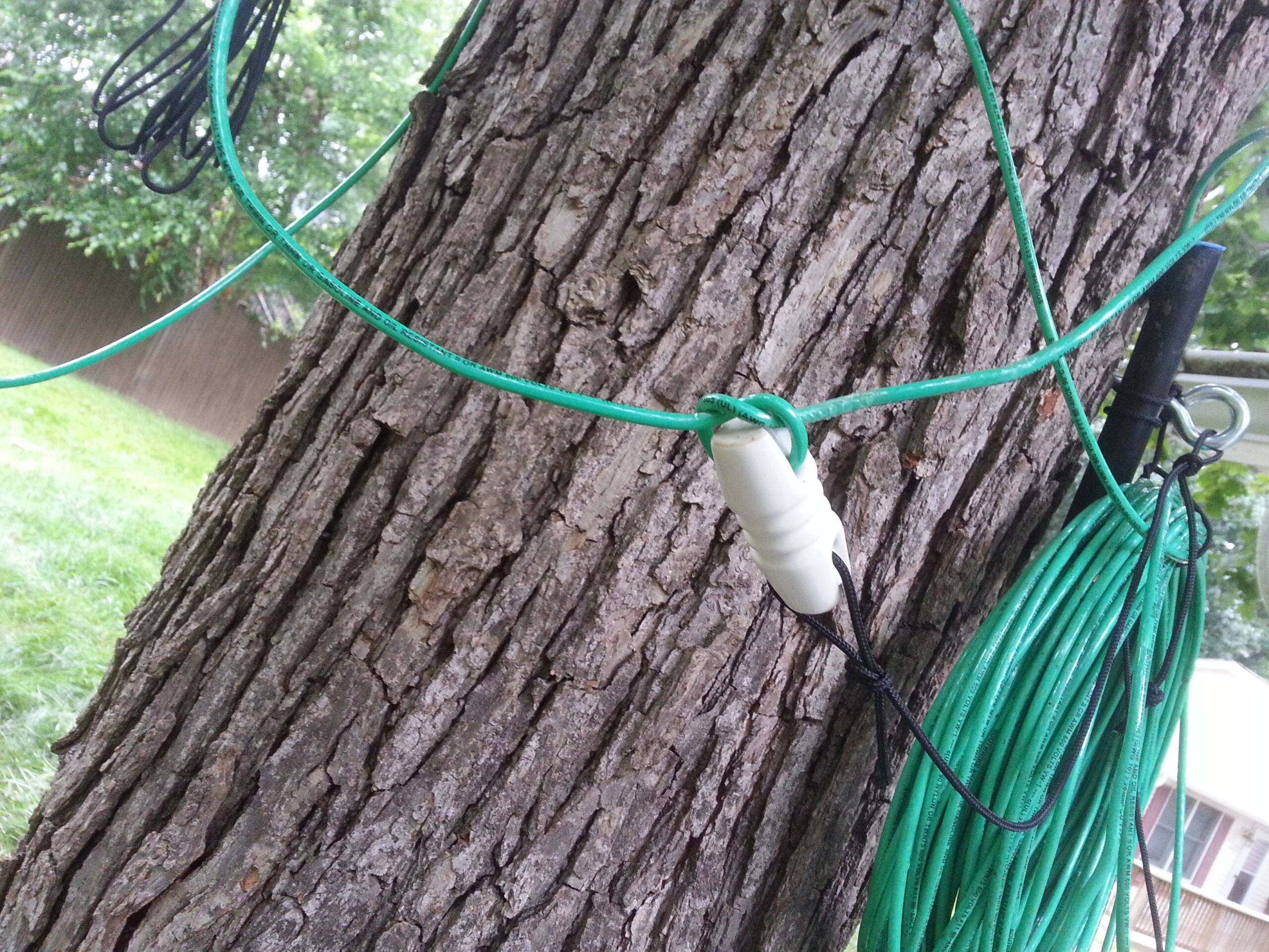
The physical installation on the trees would be done using eye-bolts. These are much easier for a tree to handle than anything tied around a branch or trunk because they create only a tiny hole which the tree can usually heal. In contrast, loop tied around the tree could eventually strangle it or a the very least impose a much larger wound that might be too much for the tree to handle.
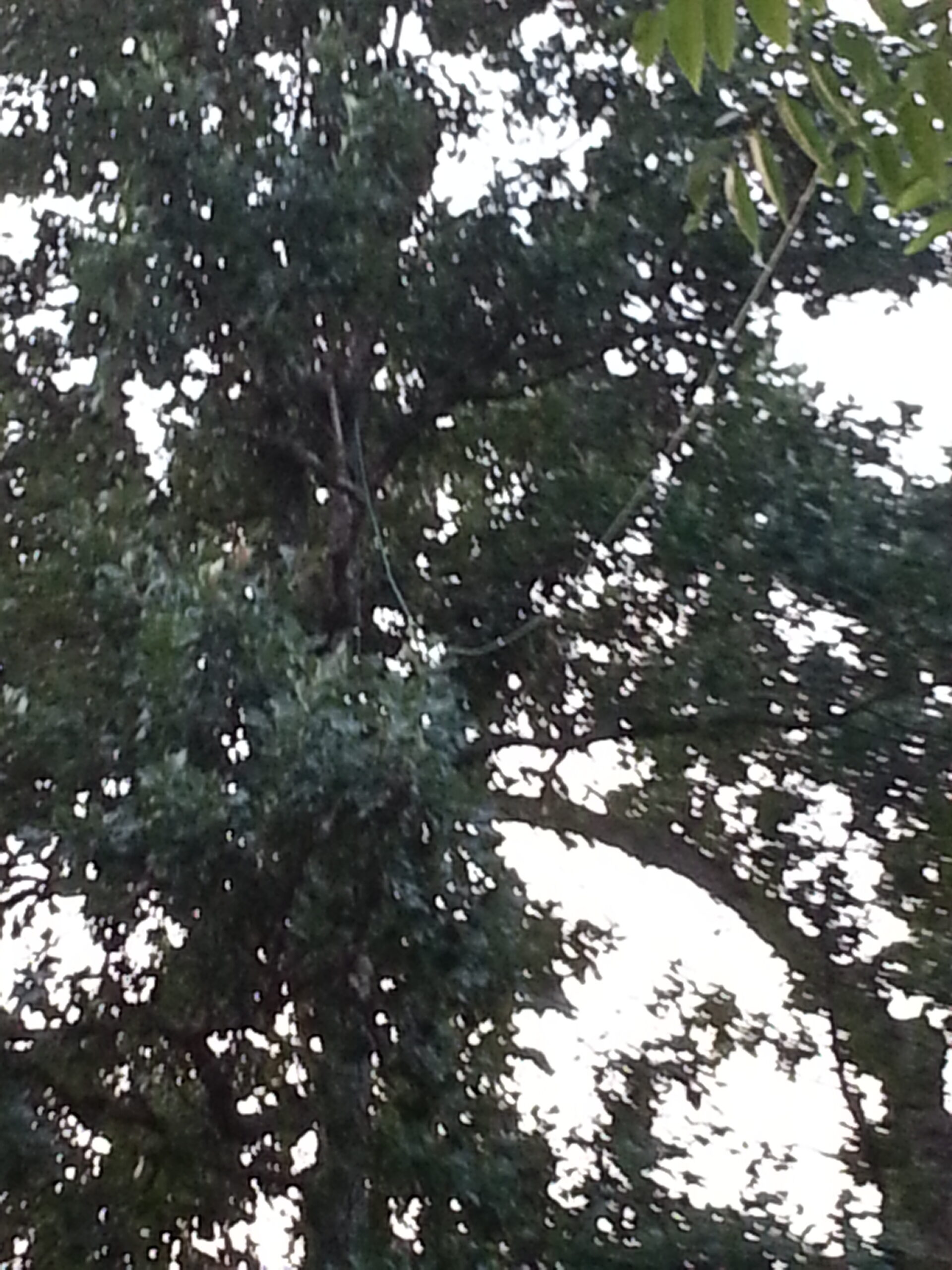
On installation day the arborist made a mistake – or more practically, uncovered one of mine. I had measured the antenna wire to precise specifications and had expected both ends of the loop to be up 30 feet. On the taller tree he installed the top pulley about as high as he could get it. My wire was too short for that — so either I would have to have him climb up again and fix it or I would have to adapt. I decided that in the end height would be more useful than precision… thus my second excursion from my usual “design first” paradigm.
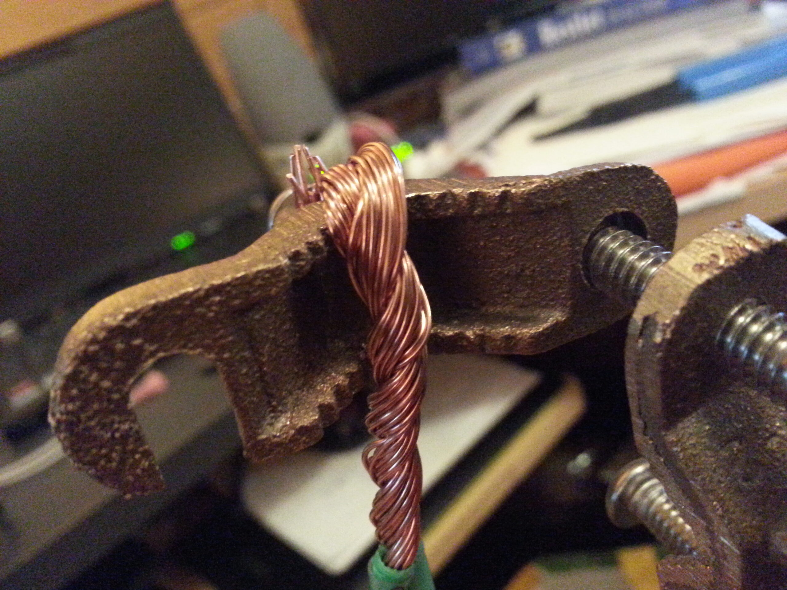
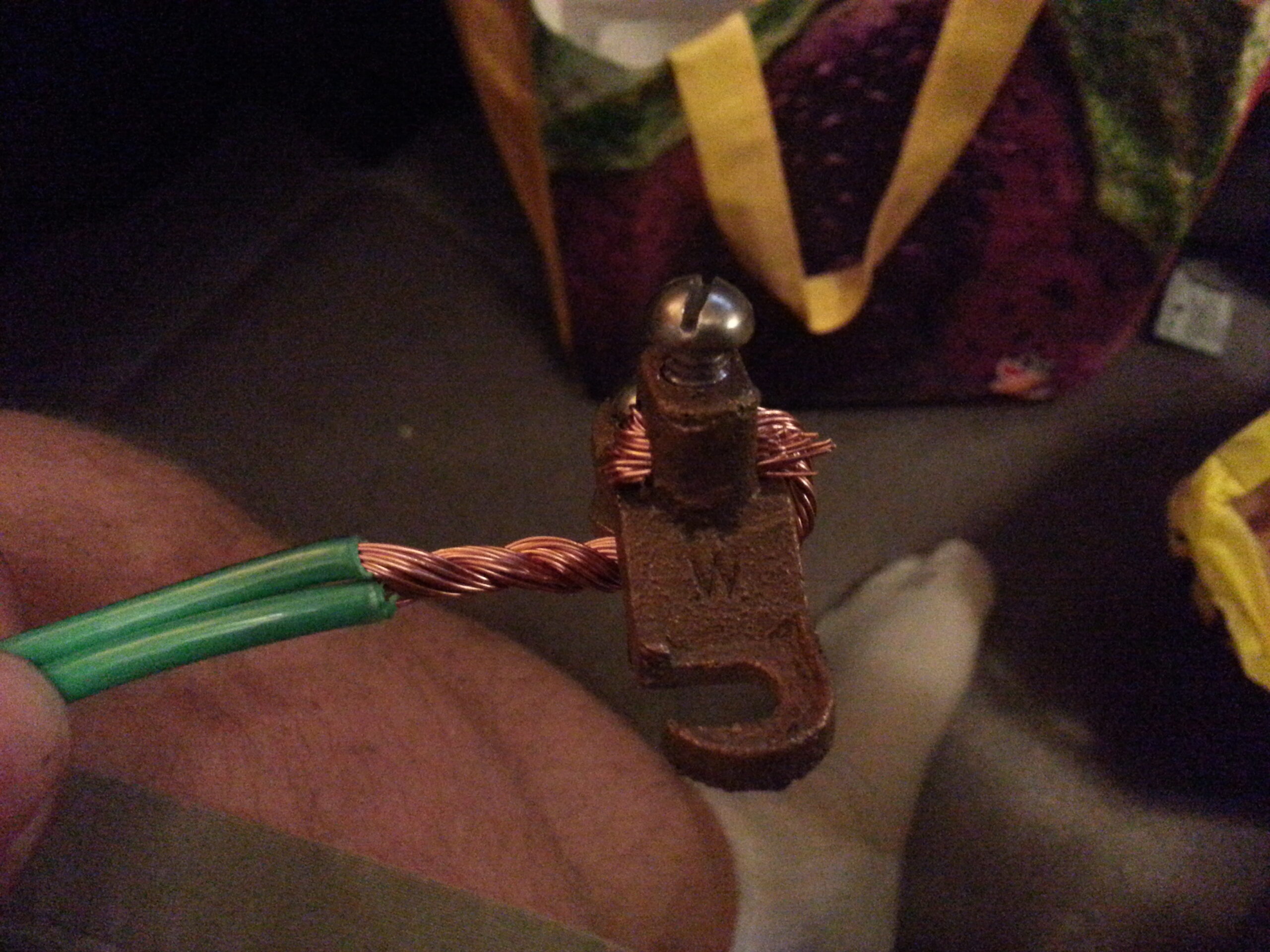
I spliced in some extra wire to make up the difference. I used a Western-Union splice, soldered it, and wrapped it in heat-shrink tubing. As it stands now the “short” side of the loop goes up about 30 feet as originally planned and the “tall” side of the loop goes up about 45 feet. The loop runs roughly east to west (120° – 300°) between the two trees – though this orientation turns out not to be very important based on the propagation data I get from WSPR results.
The wire is hung with sufficient slack to allow the trees to sway in the wind without ever creating a high tension on the wire. This is much easier in this case than trying to configure some kind of weight or spring mechanism. As it turns out the extra slack doesn’t seem to affect antenna performance very much, and since this installation has now survived several years (initially built in 2014 and it is now 2022) the physical installation seems quite sound.
It’s probably also worth pointing out that the vertical portions of the antenna are running up the trees, and yes the bottom is technically under-ground. Shouldn’t that be a problem? Trees are conductive (sort of)! and the bottom of your loop is in the ground!! Are you mad!!??.
Yes, yes I am, and, it doesn’t matter 😉 This was never going to be a perfect antenna, just a good one. The tuner does a fantastic job of figuring out the various vagaries of the adjacent conductance of the ground and trees; and in the end the performance of the antenna turns out to be quite good in all weather.
Ultimately, though it might be fun to have an antenna farm where I could perfectly build all of my crazy ideas, I must bend to practical circumstances. What is kewl about this design is that almost anybody could build it almost anywhere and expect reasonably good performance. I’ve even considered using something like this on field day by just laying the bottom half of the loop on the ground stretched between a couple of cinder blocks. If I ever get to try that I’ll let you know how it goes– but it should work, and basically just requires a couple of reasonably high vertical points, a tuner, and a spool of wire.
The tuner box and various electrical conduit and outdoor boxes come from home depot. The goal is to keep the weather out and keep the electronics happy. That turns out to be pretty hard to do as the weather is relentless – so I decided not to skimp very much on these parts.
The tuner is an SGC SG-237. Currently I’m running the second of these devices on the antenna. The first one “went deaf” a couple of years ago for unknown reasons. I recently replaced it with an identical model. Testing that and being reminded of the antennas’ performance is what prompted me to finally publish this article.
The tuner goes in a weather proof box that’s large enough to house any additional equipment I might want to post outside on the tree. In addition to the feed line and control wiring I also pushed a cat-5 cable out to the box in case I want to run some POE driven computing gear and other devices. So far, I’ve not done that, but I do have ideas.
A second insulator acting as a strain relief is mounted on the antenna above the tuner box so that the wire doesn’t pull on the box nor the tuner.
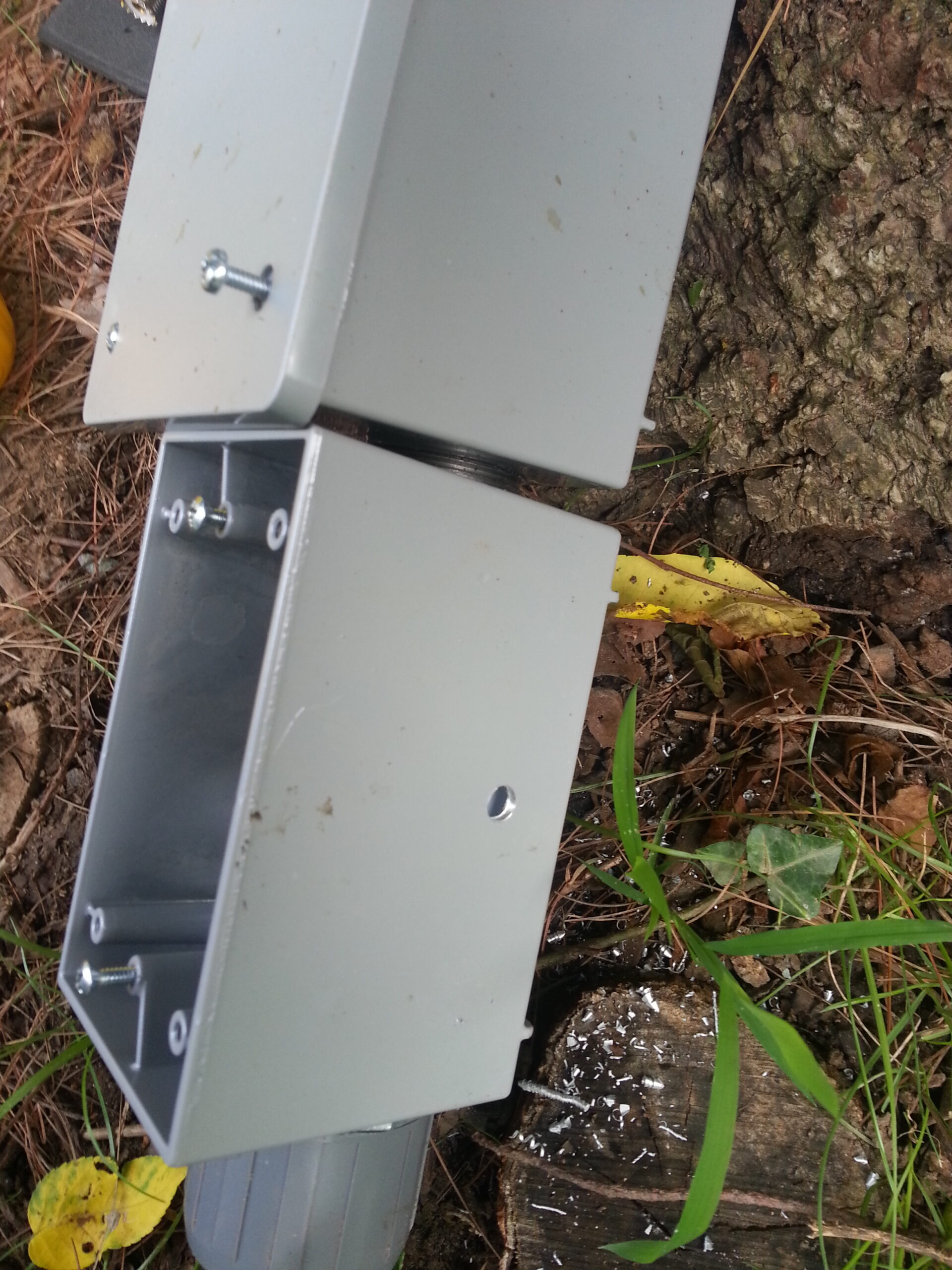
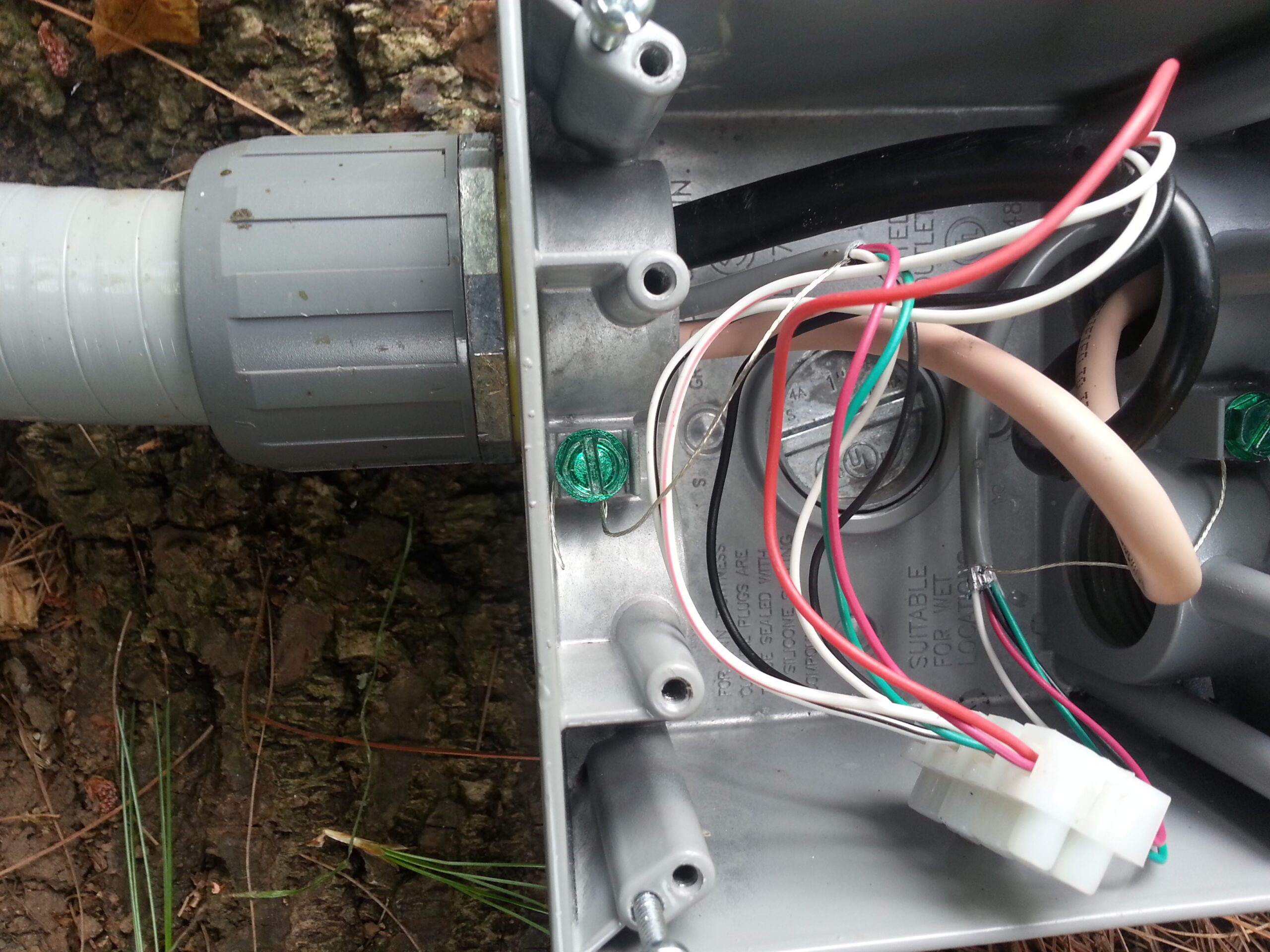
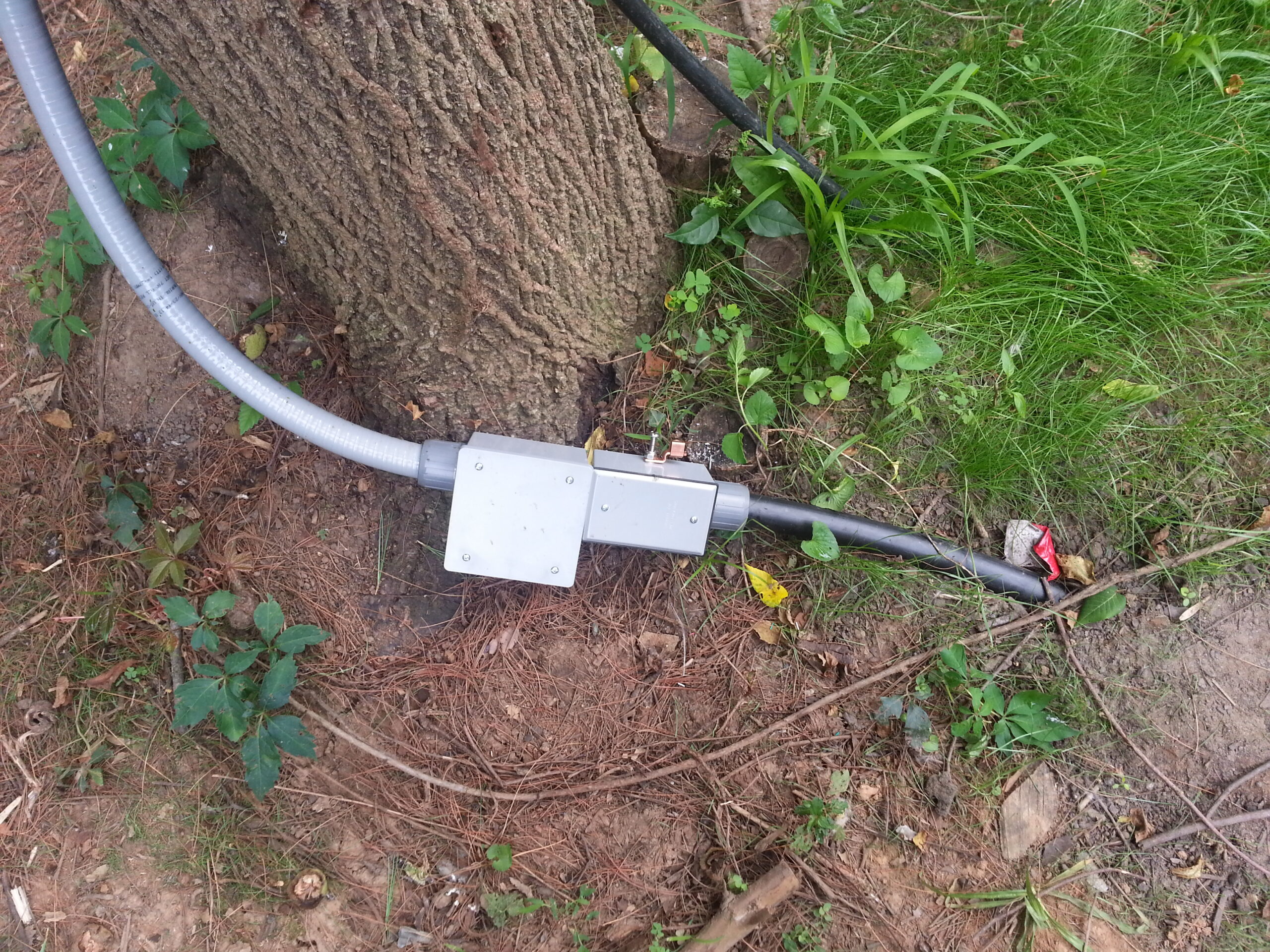
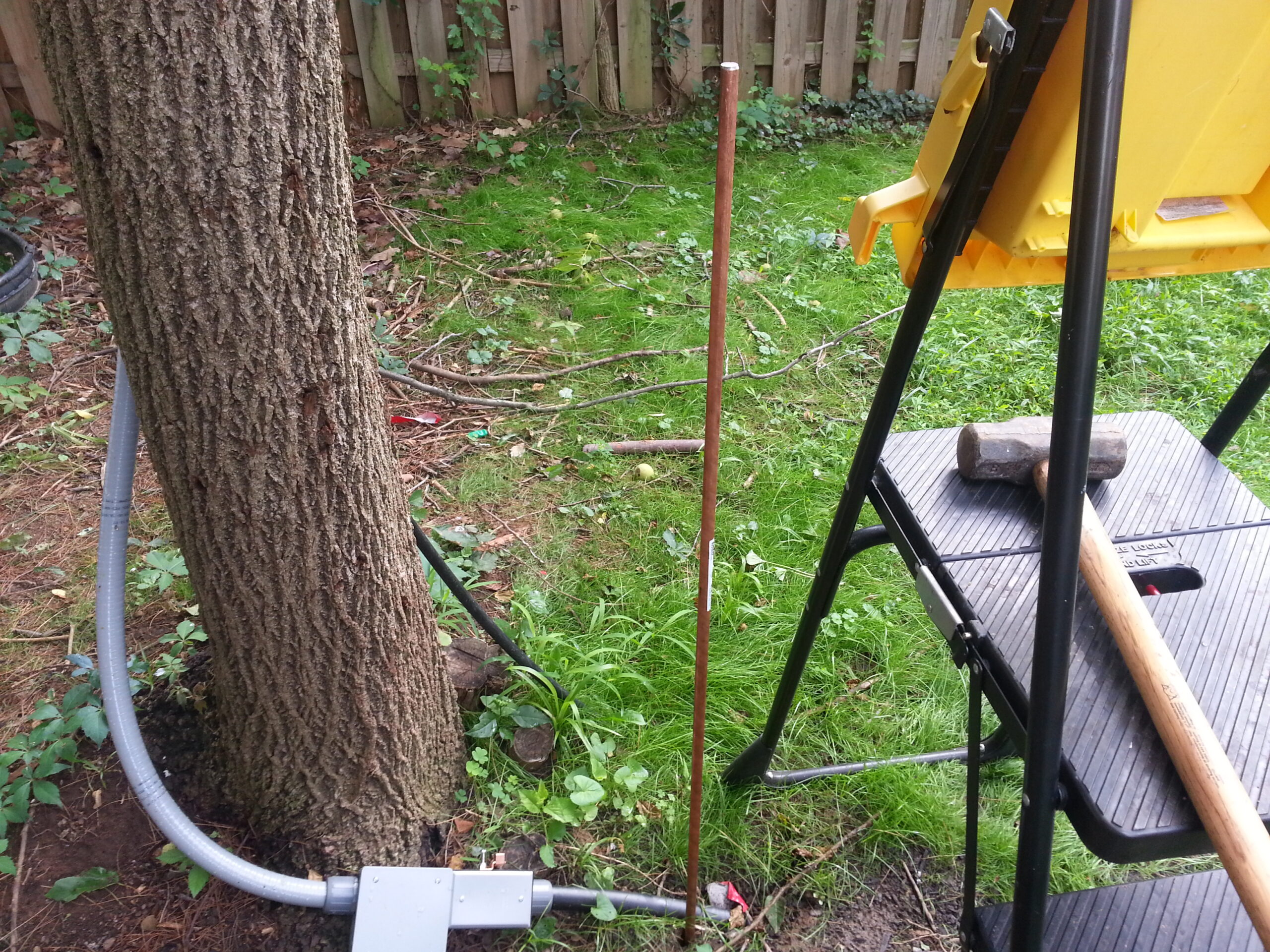
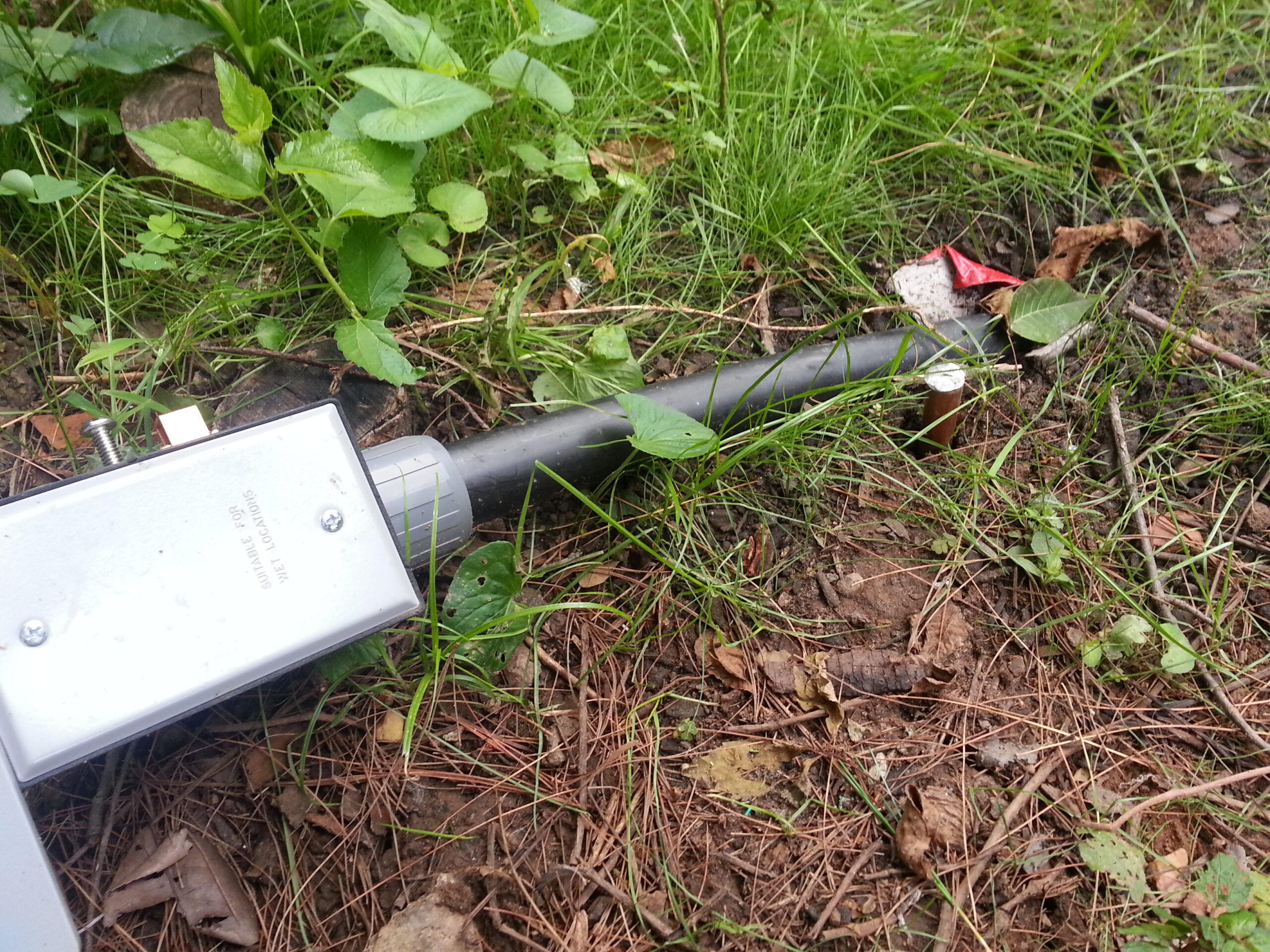
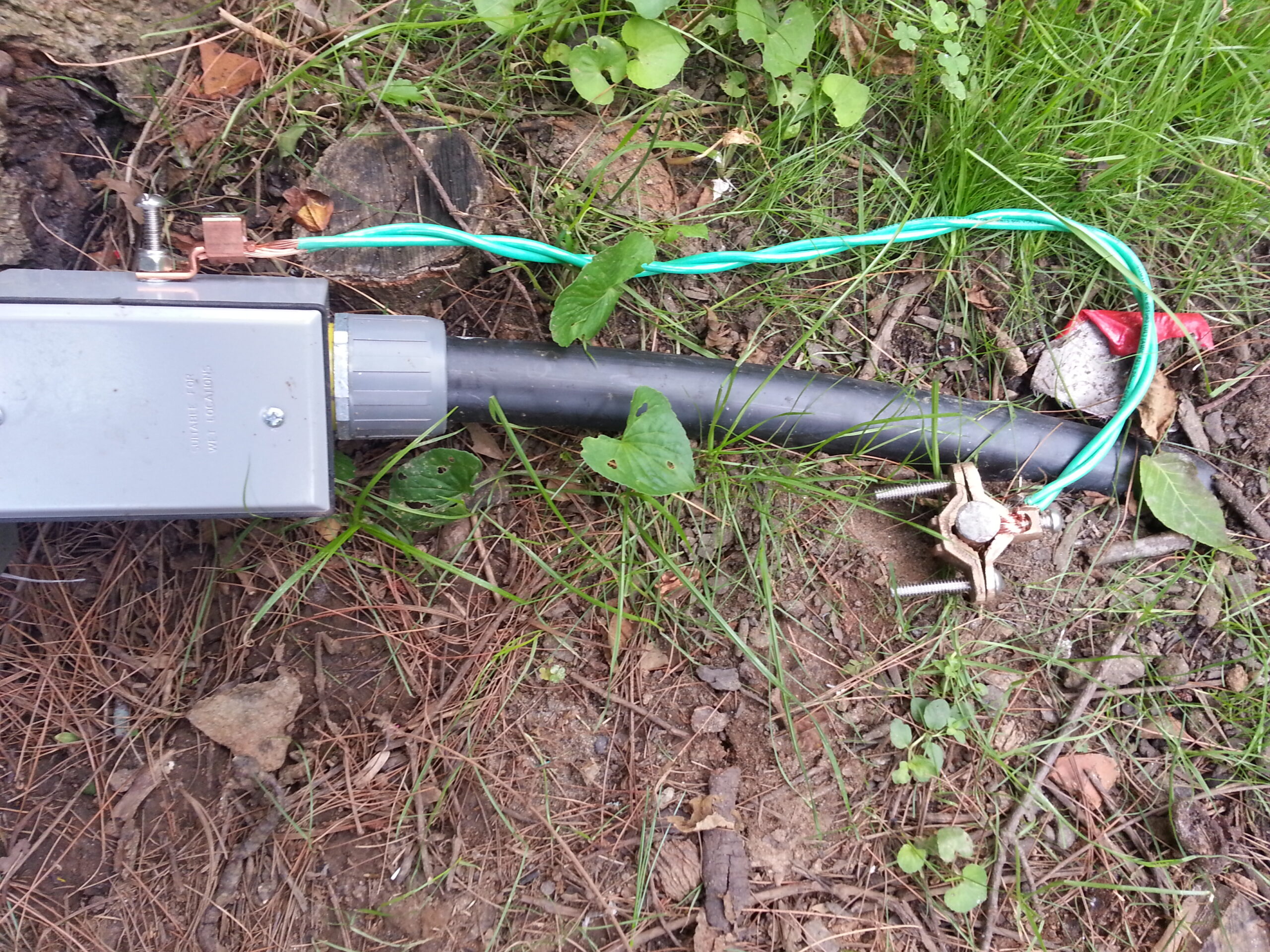
In order to keep things serviceable and to provide some safety I installed a couple of boxes at ground level between the sprinkler tubing that goes to the lab and the outdoor electrical conduit that runs up to the tuner box.
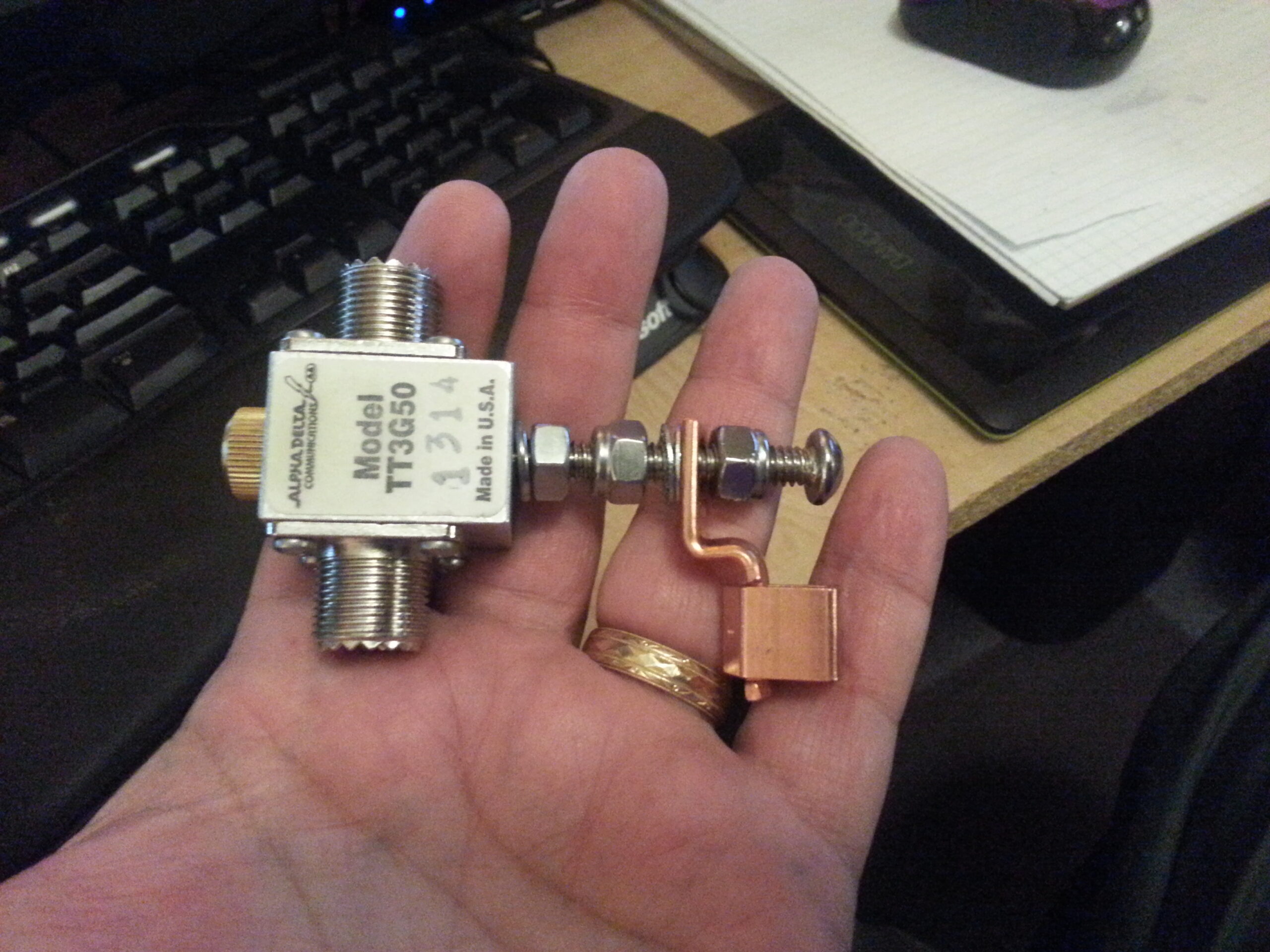
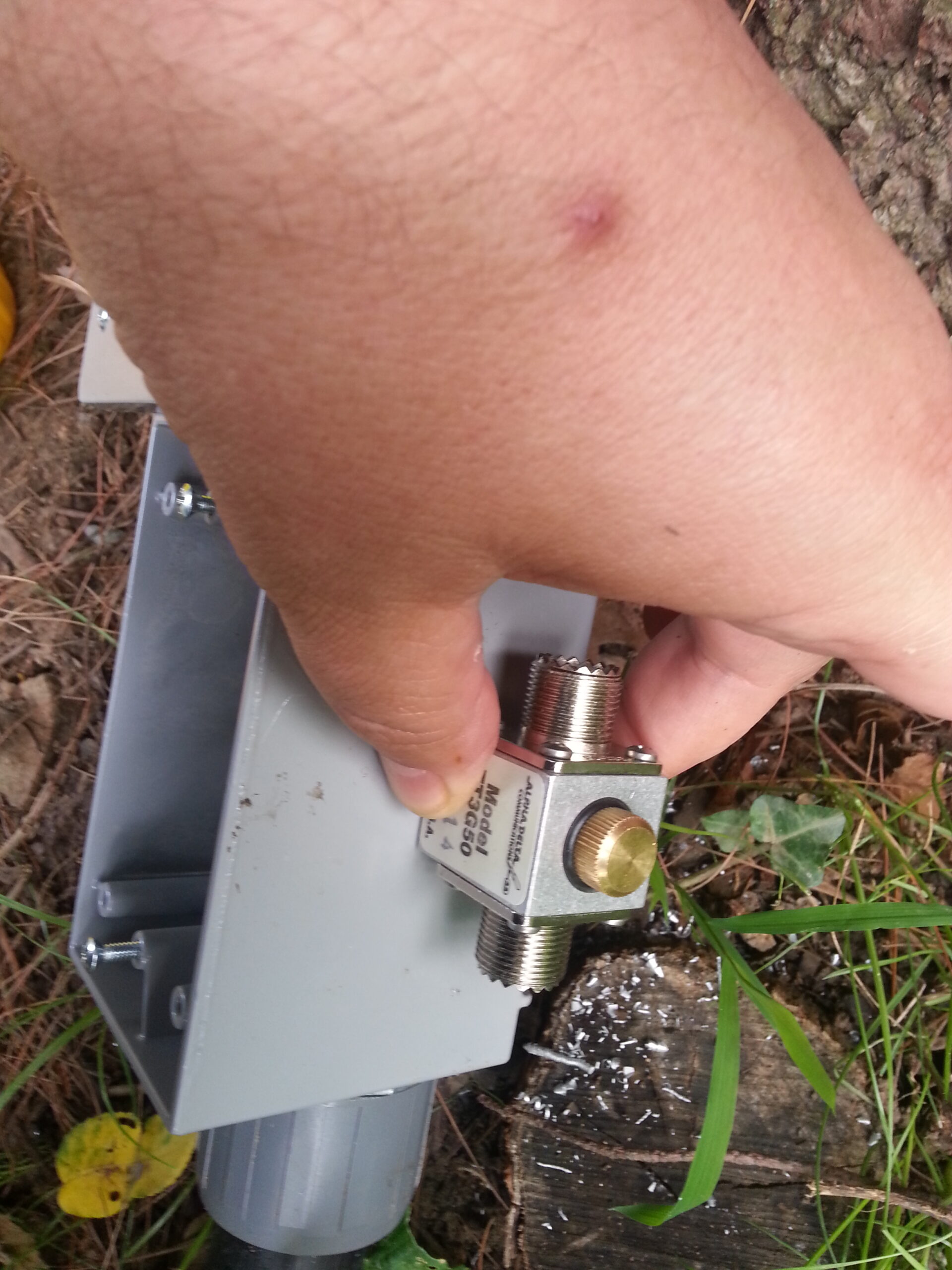
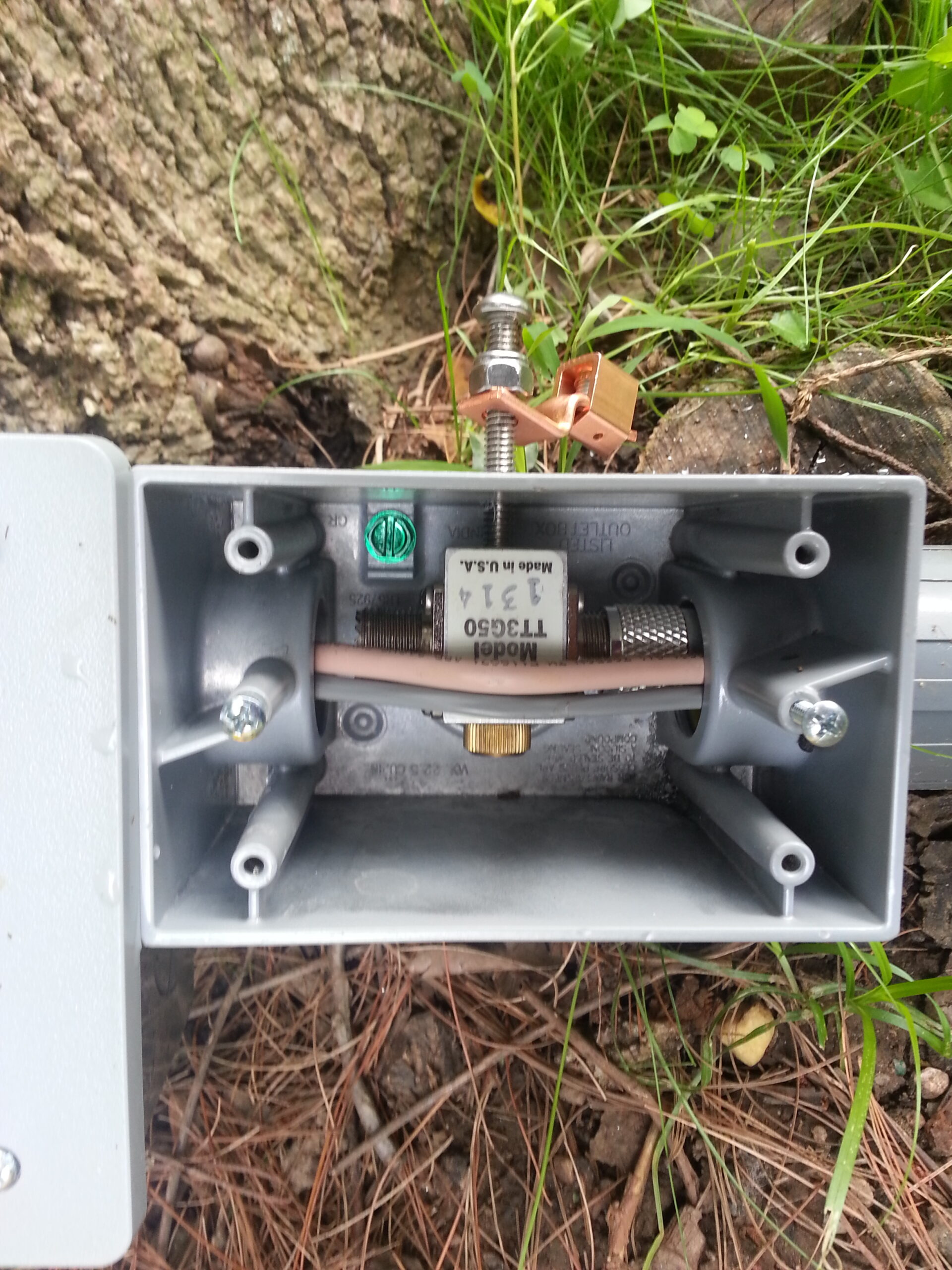
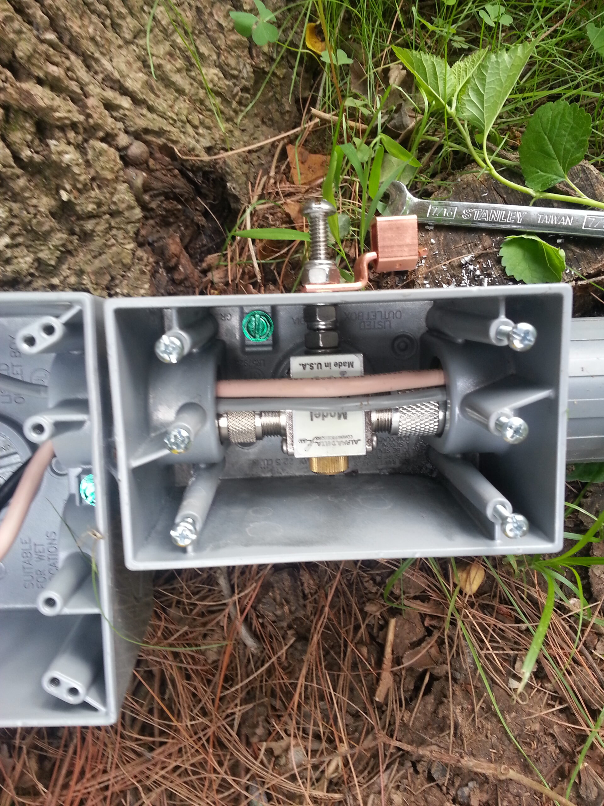
One of these boxes acts as a connection point between the control cable from the lab and the control cable coming from the tuner. The other box connects the feed line from the tuner with the feed line from the lab via a lighting arrester: Alpha Delta model TT3G50.
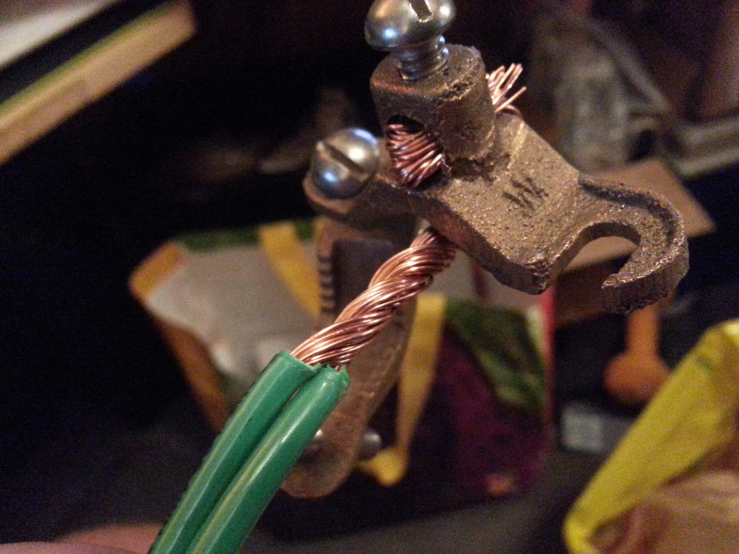
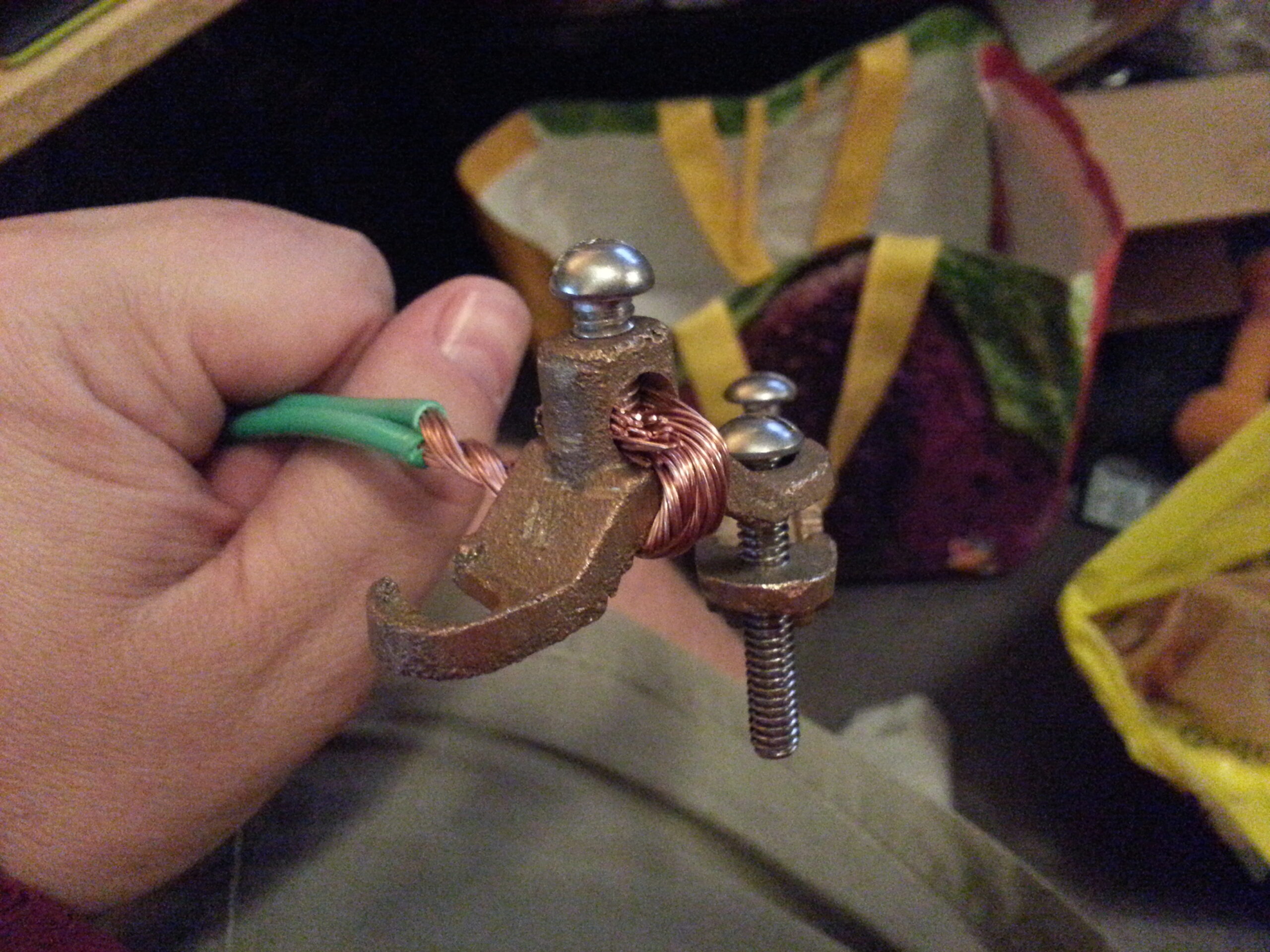
All of these are grounded via an 8 ft ground rod driven at the base of the tree right next to the boxes.
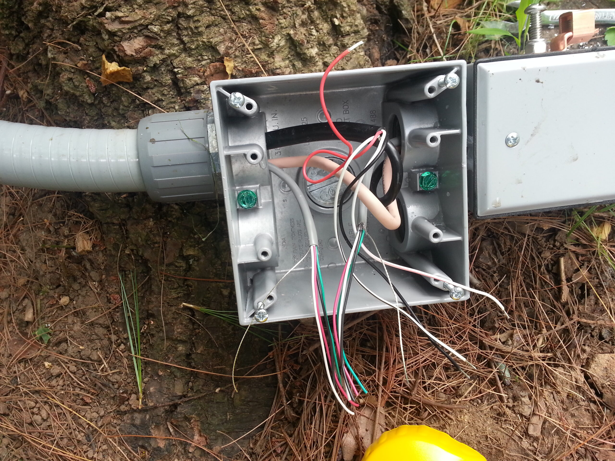
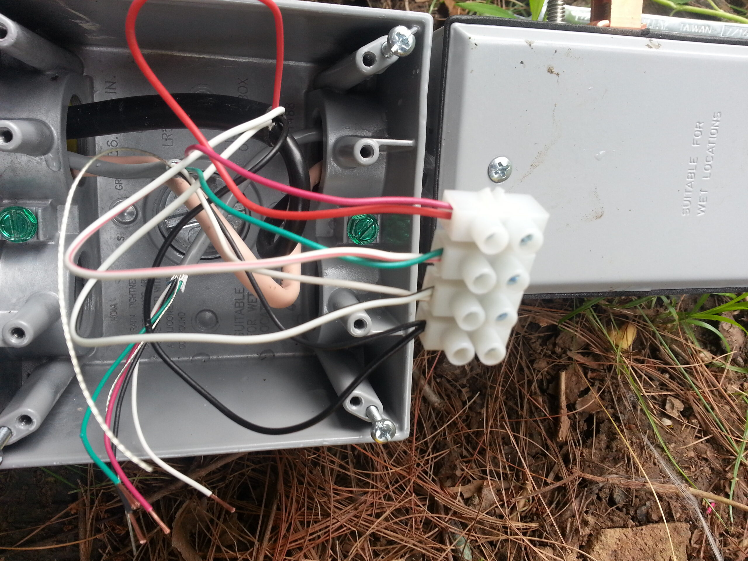
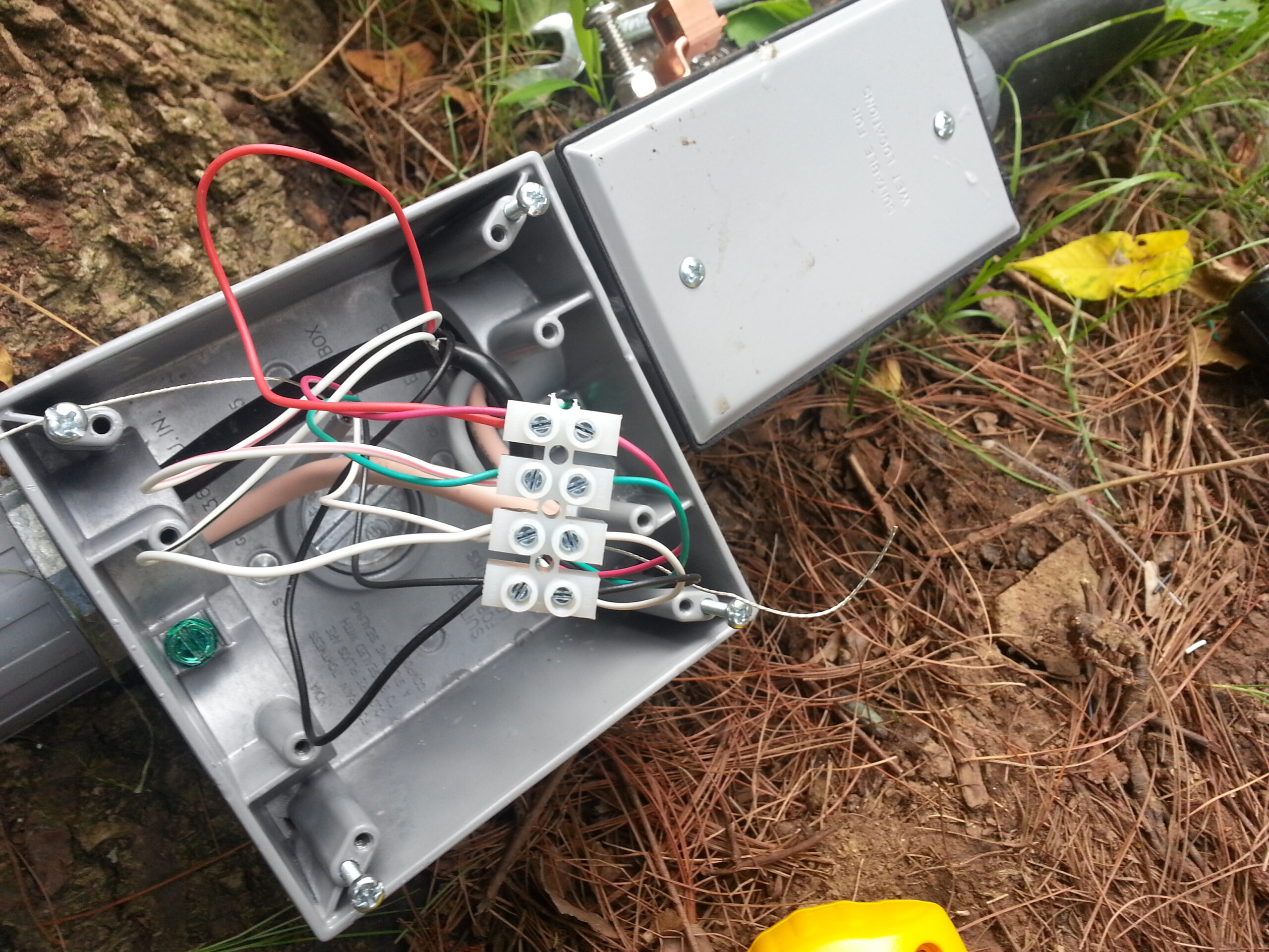
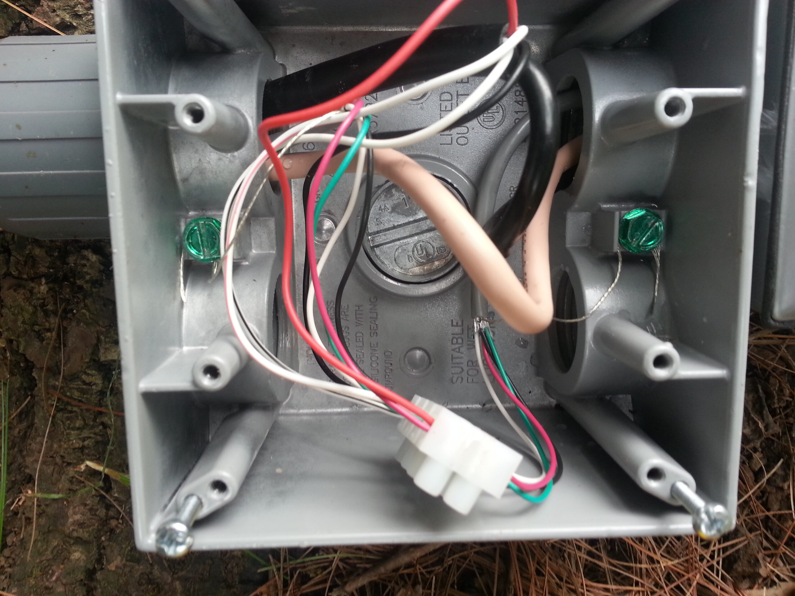
Lately I’m re-thinking the screw terminal strip for the control wires and considering replacing those connections with heat-shrink soldered connections. It turns out that the time between servicing these connections is fairly long and I’d like to have better long-term connectivity than I can expect from screw-down terminals.
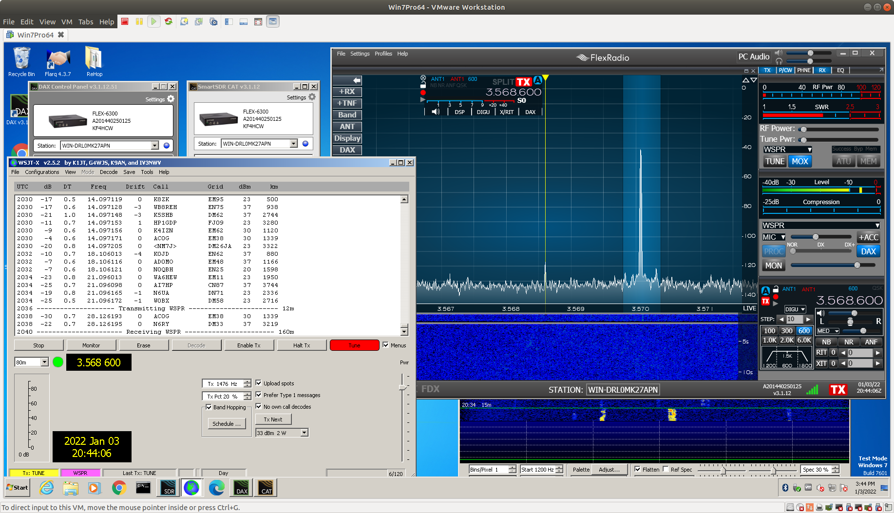
When I’m not otherwise using the HF rig I generally run WSPR continuously. Since the tuner refit I’ve been running WSPR at 2 watts on all HF bands with some pretty spectacular results. I can expect to see contact to Australia, Hawaii, Europe, Africa, the Arctic and Antarctic on a daily basis – usually on multiple bands.
The sweet spot for the antenna seems to be 17M but all bands 160 – 10 are usable, and 20-15 are quite good (sun spots permitting). The worst SWR I get is on 80M at about 2:1.
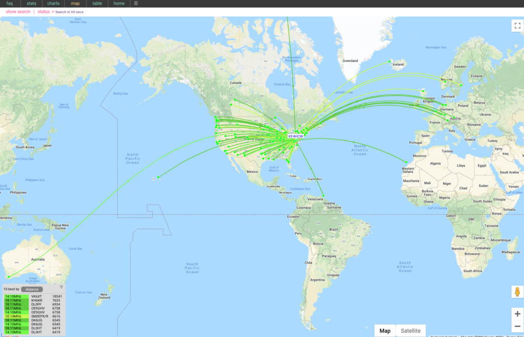
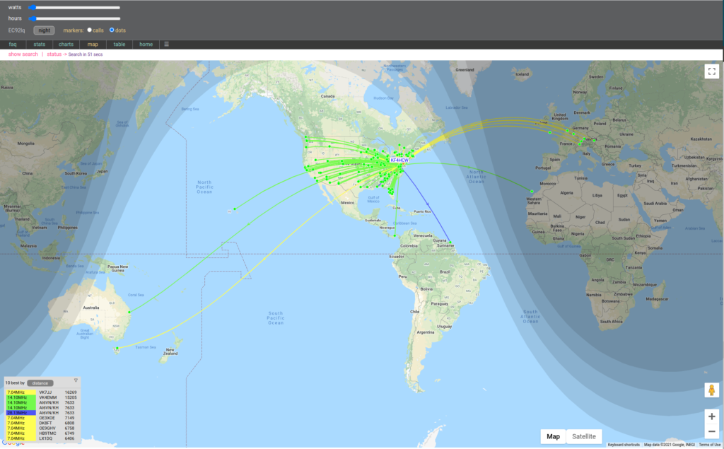
Here is a tweet I posted showing good DX WSPR contacts on 3 bands simultaneously. If you build something like this please do let me know how it works for you.