At the heart of the “big loop” antenna is the SG-237. Click here to see the manual for that.
The tuner can be run without a controller, but it offers a few features with a controller that are useful (and sometimes important) in practice. I took a look at the controller suggested in the manual and re-designed it a bit to better suit my purposes. First, because I wanted to use parts that I had laying around the lab, and second because I wanted a better “light-show.”
The important features are:
- You can tell the tuner when NOT to tune. I find in practice that this can be particularly important when running digital modes as switching things around at the antenna can inject unwanted noise to your transmitted signal.
- The tuner can tell you when it’s found a good tuning solution. Sure, it seems like this would be obvious enough once the SWR stops bouncing around… but it is awfully handy to have a nice green light tell you when the tuner has stopped looking.
- I found this out AFTER I built my controller – The tuner can tell you when it didn’t find a solution but has given up trying! On my tuner controller there is an amber light for when the tuner doesn’t yet have a solution and a green one for when it has found a solution. One day I saw these flashing back and forth like it was shaking its’ head. I figured out that’s what it does when it gives up trying. This doesn’t seem to be documented anywhere, but it’s also a nice feature.
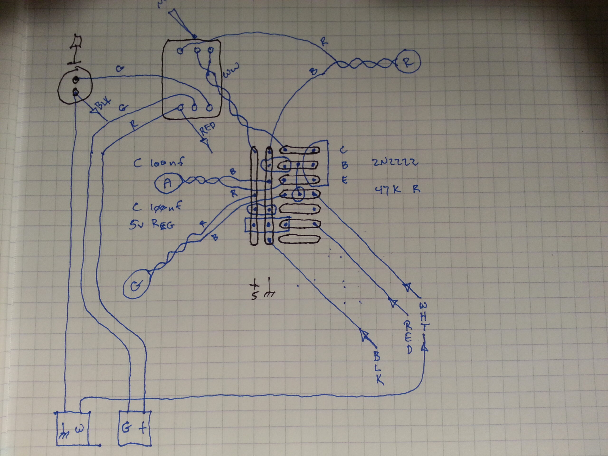
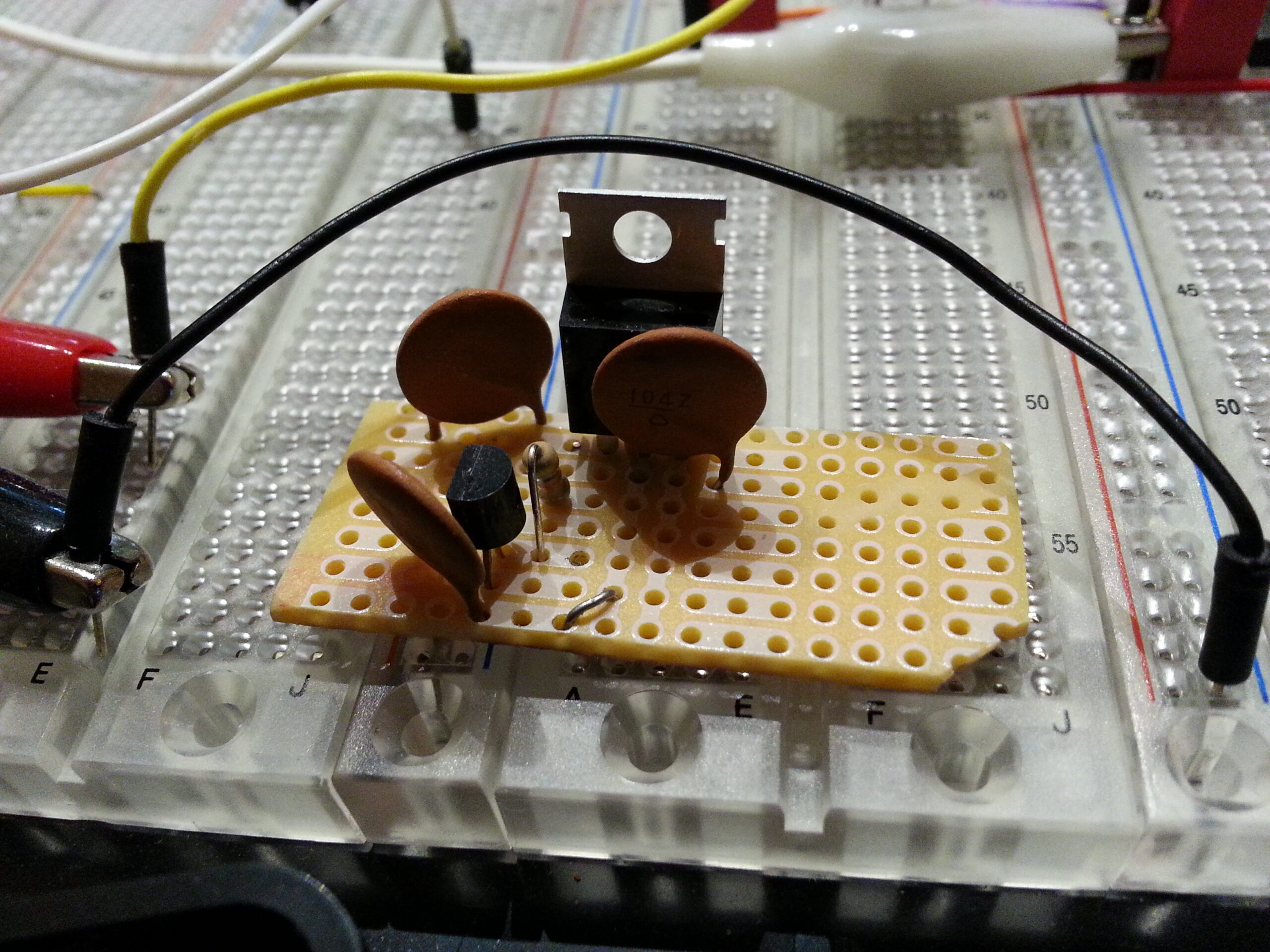
The first step was to draw up a schematic for the circuit and do a little math to make sure everything would work.
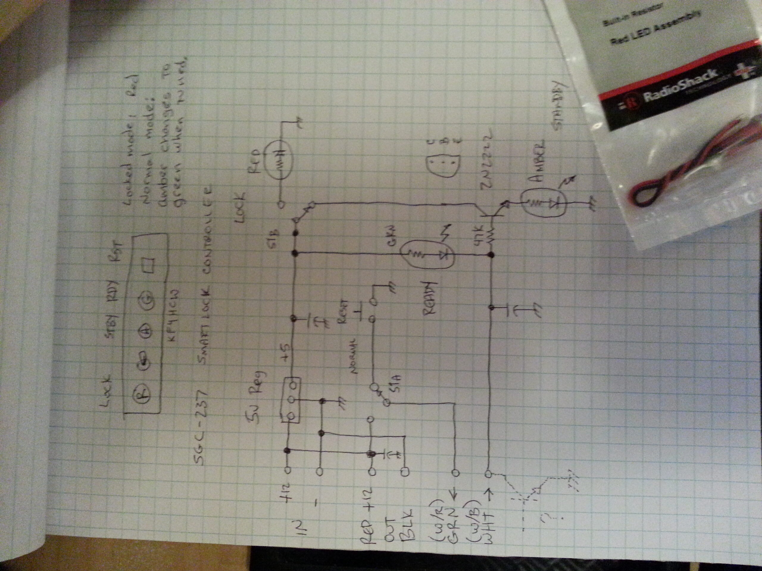
In the controller recommended in the manual they roll their own ~9 v regulator using a zener diode and an NPN transistor. They only use this to drive their LEDs, so I did something similar but instead used an actual 5V regulator.
The next thing I changed was the “tuned” indicator logic. Their controller pulls one side of their tuned indicator to ground when the tuner is happy. I presume this is done through something like an open collector in the tuner.
I wanted two lights instead of one so I added a 2N2222 transistor and a resistor to turn on an amber “not-tuned” LED when the green “tuned” LED is not on. Basically, the green LED and its’ current limiting resistor act like a pull-up resistor to bias the transistor on whenever the “tuned” LED is not pulled to ground by the tuner. The 47K resistor in series with the base ensures that any current that flows is tiny enough that the green LED won’t light (at least not in a way you can see it). The gain of the transistor is high enough that it will still effectively saturate in this condition thus turning on the amber “not-tuned” LED.
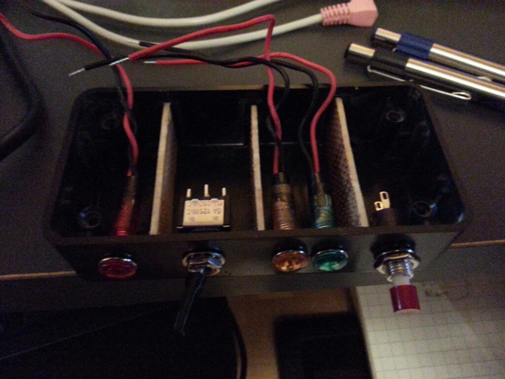
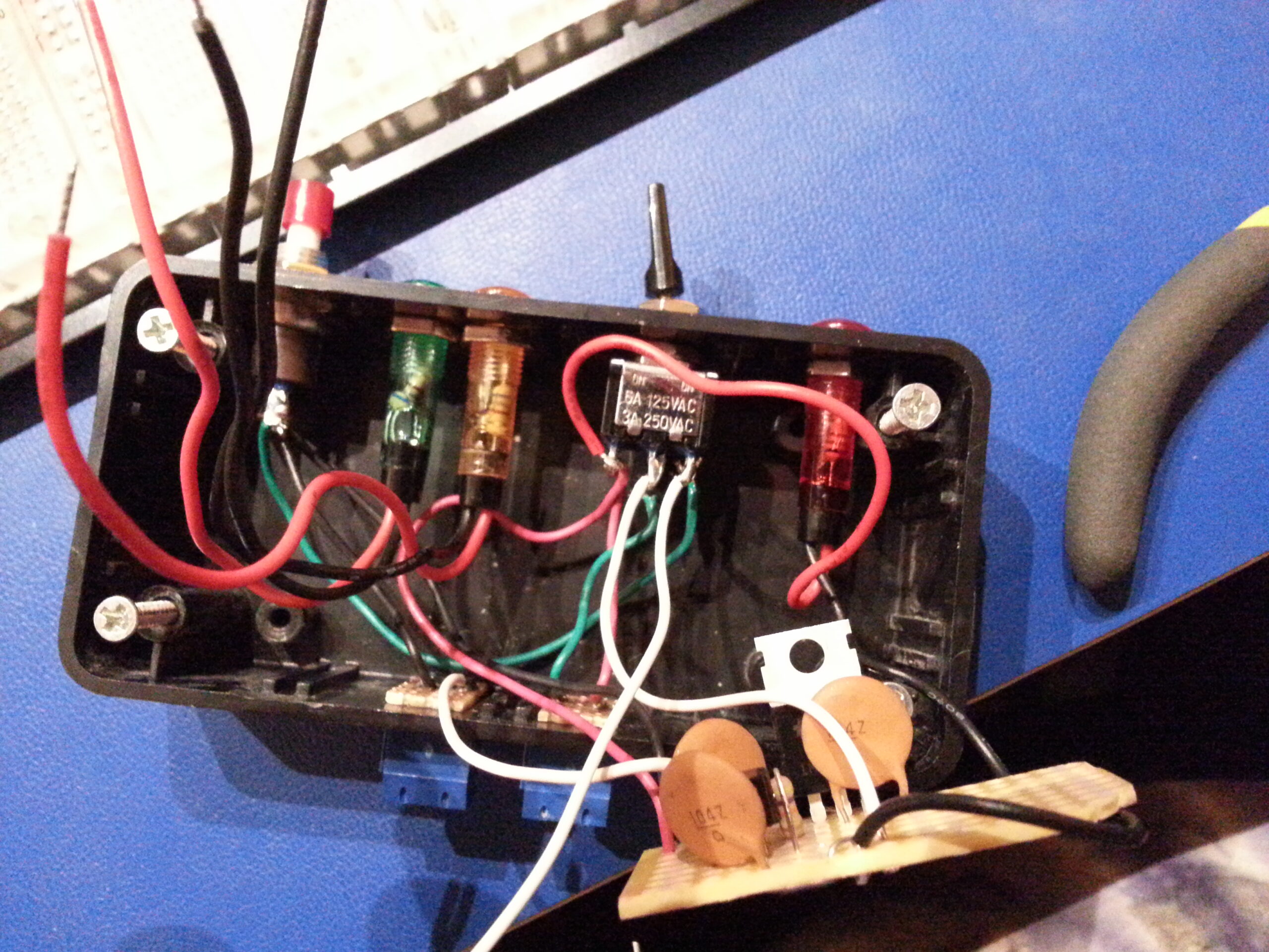
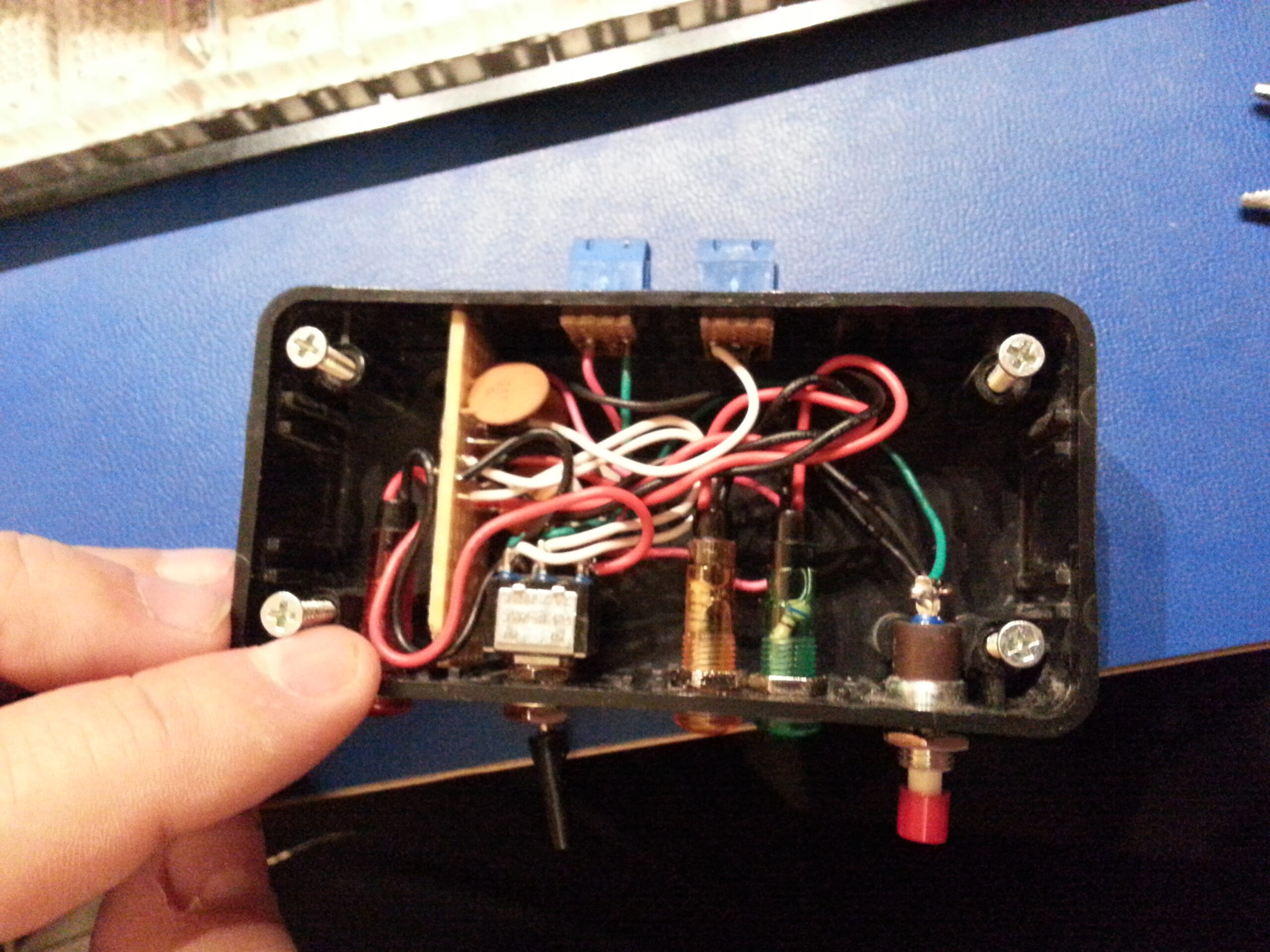
The rest of the circuit is essentially the same as their controller – so the tuner sees almost precisely the same signals. This consists of a DPDT switch, a momentary SPST push-button, and a handful of decoupling caps. All of this, a handy box, and some LEDs with built-in current limiting resistors were all handy in my lab… courtesy of the recently (at the time) defunct local Radio Shack – and my irresistible urge to grab everything I could from them in their last days.
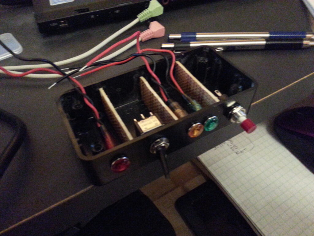
Once the design was done it was time to put the mechanical components into the box and see how they all fit. Here is where some on-the-fly creativity was required because one cannot always be sure what parts they have nor how they can be used to solve a particular problem… I mean, I wasn’t building this from a BOM where I could order up precisely what I wanted right?! I had to see what I had around and improvise with that.
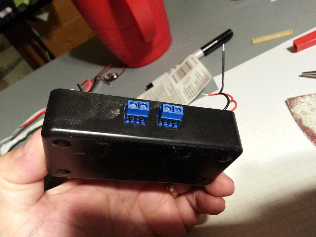
As it turns out all of the parts I had handy fit perfectly including some PCB mounted screw terminals that I was able to adapt to the back of the box with a little bit of drilling, sanding, and some small pieces of protoboard.
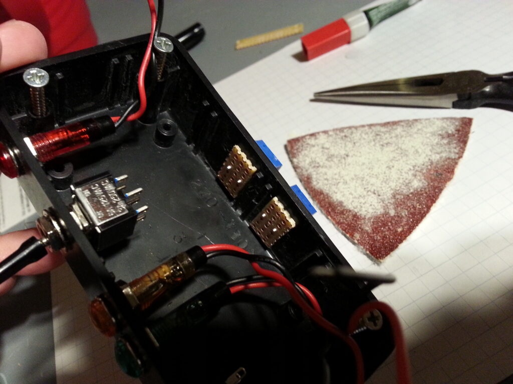
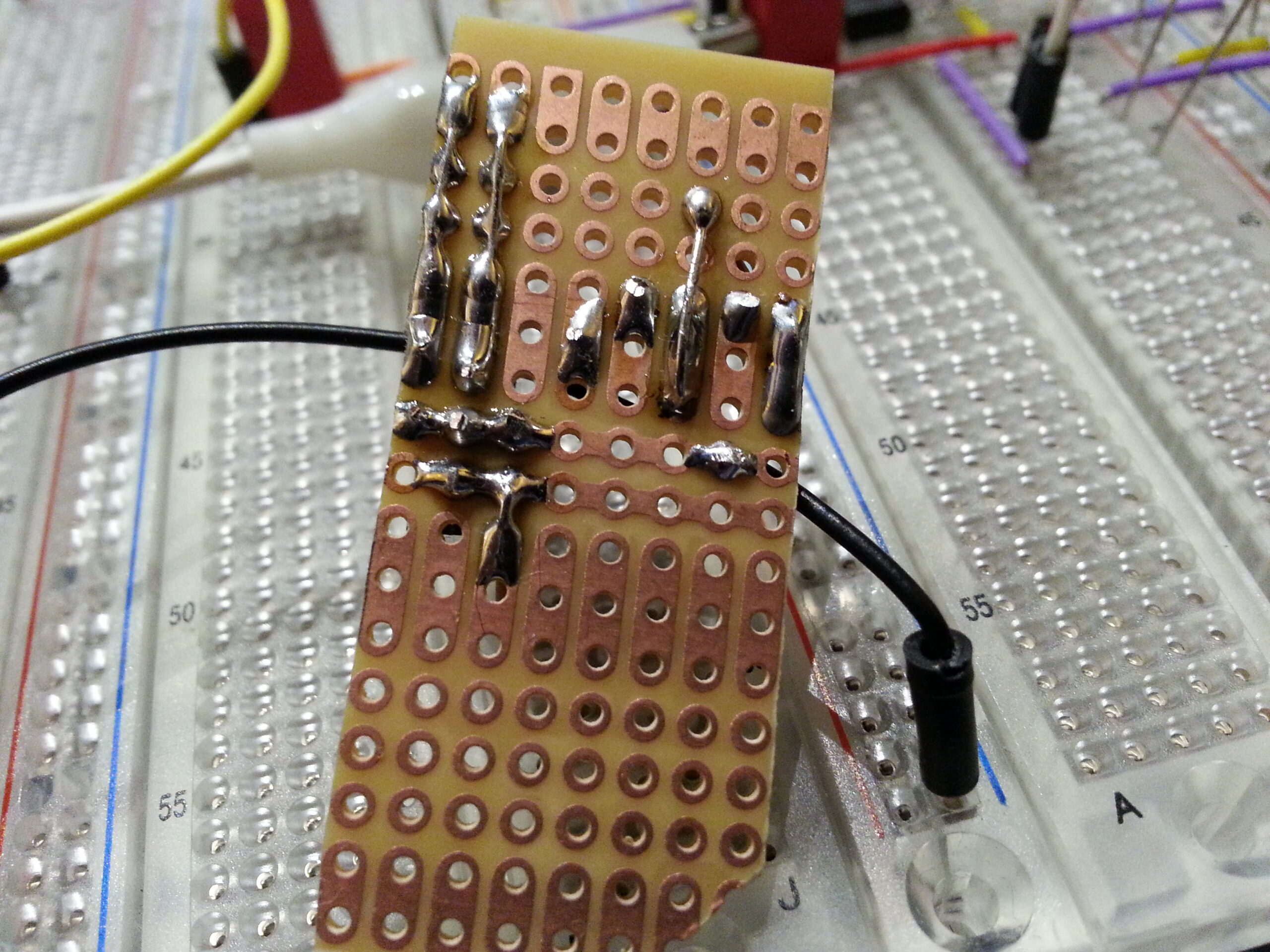
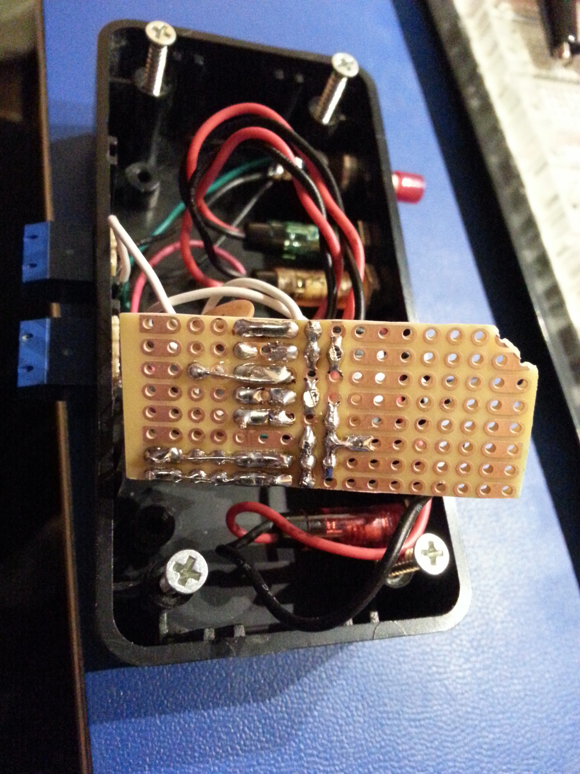
Next up I designed the layout of the electronics on another piece of proto-board. It’s always a good idea to take this extra step rather than going directly to soldering parts in place – even on something simple like this. The end result almost always turns out better and cleaner for the extra effort.
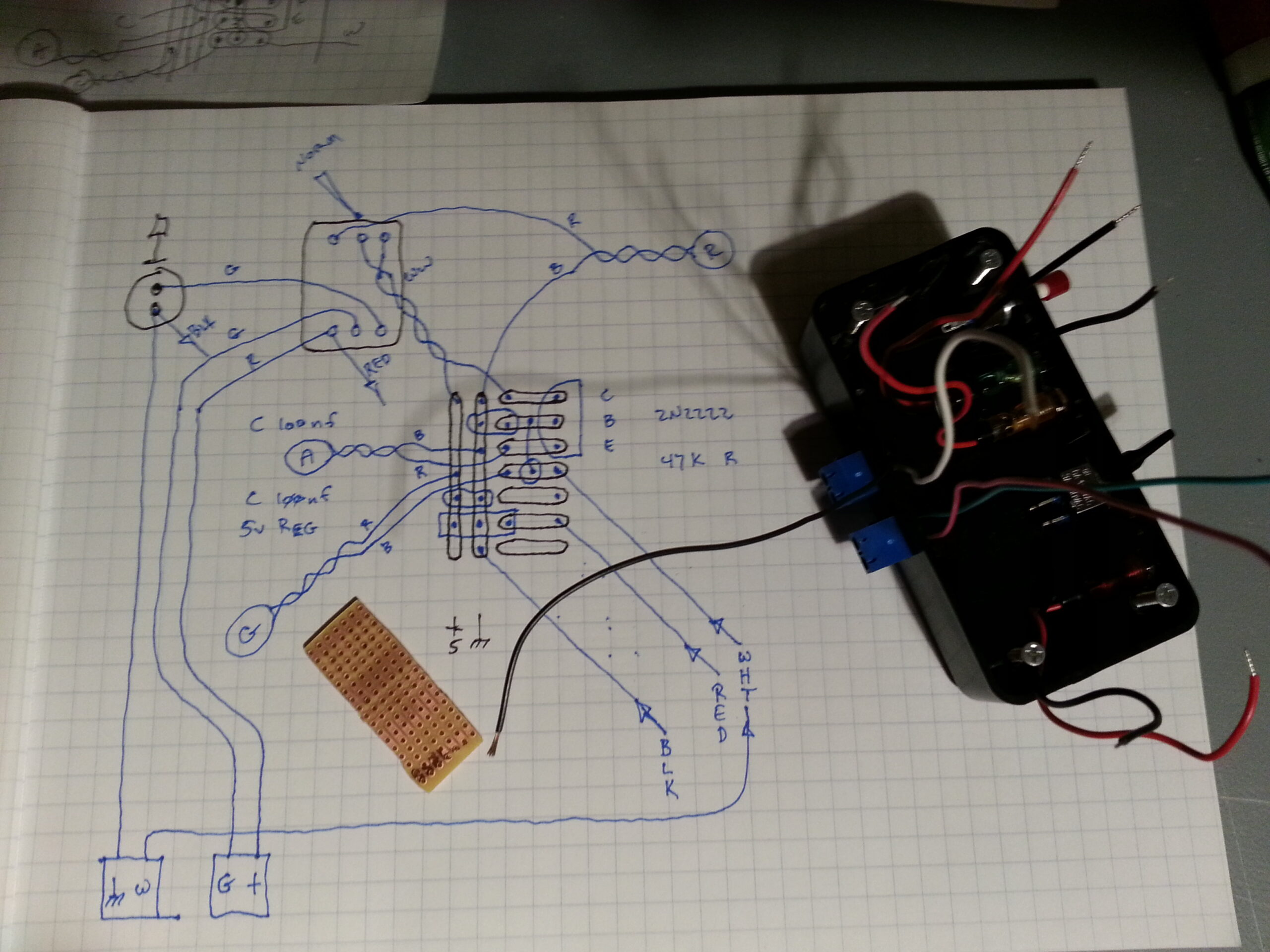
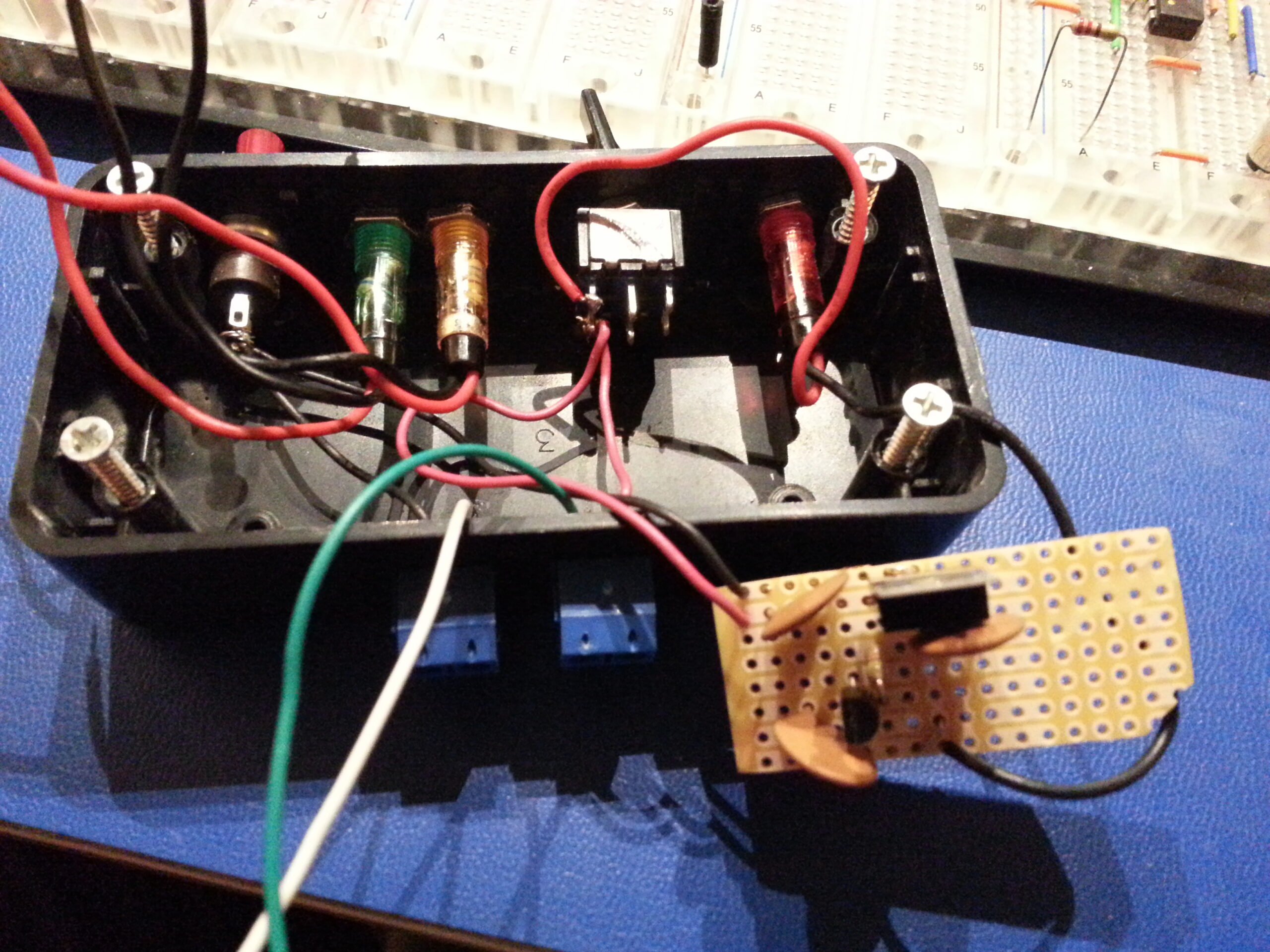
Then, once I’d put all of the parts in place I made a few measurements (idiot test) to make sure I got it right. A quick look at the box also informed me that I was going to need to make a notch somewhere on the board so that the wires from red LED could get to the other side. The simplest solution to that was to knock off a corner of the board.
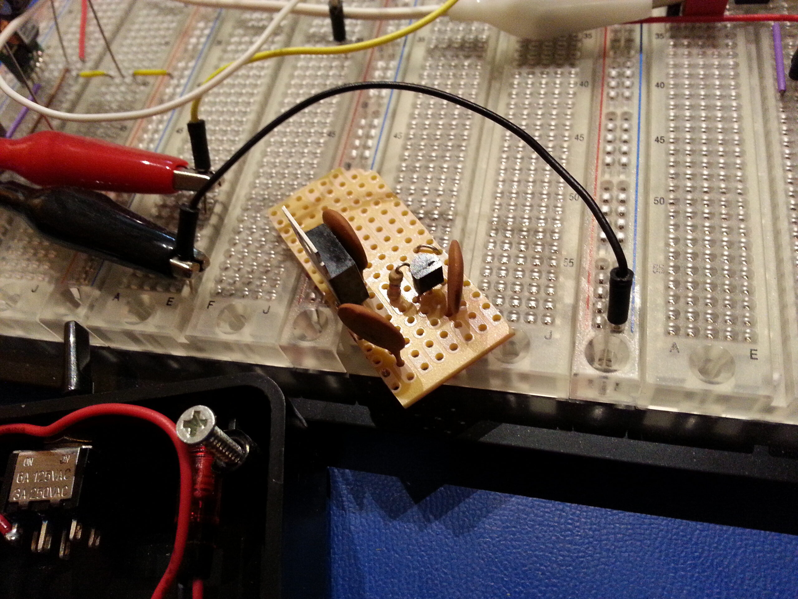
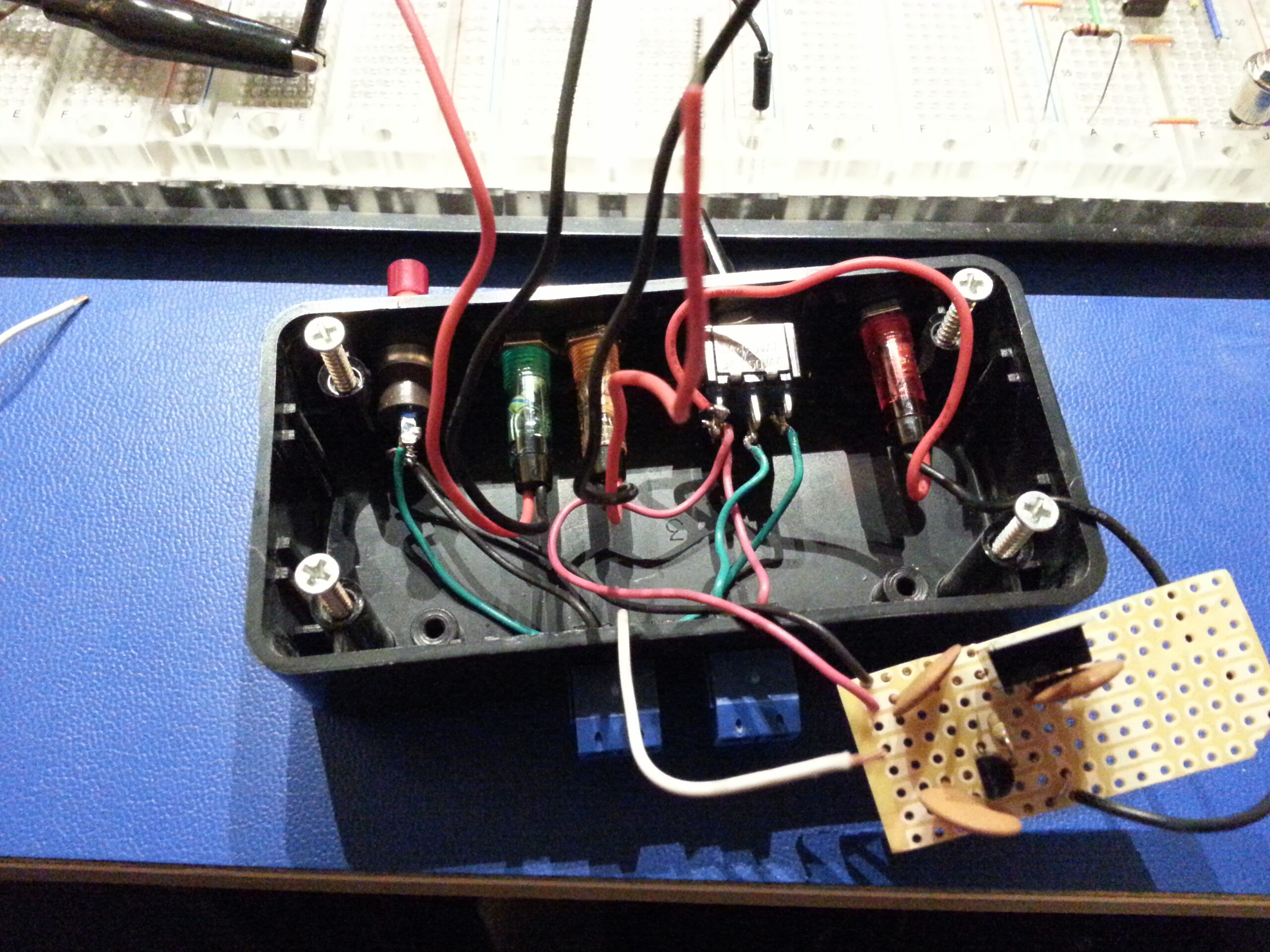
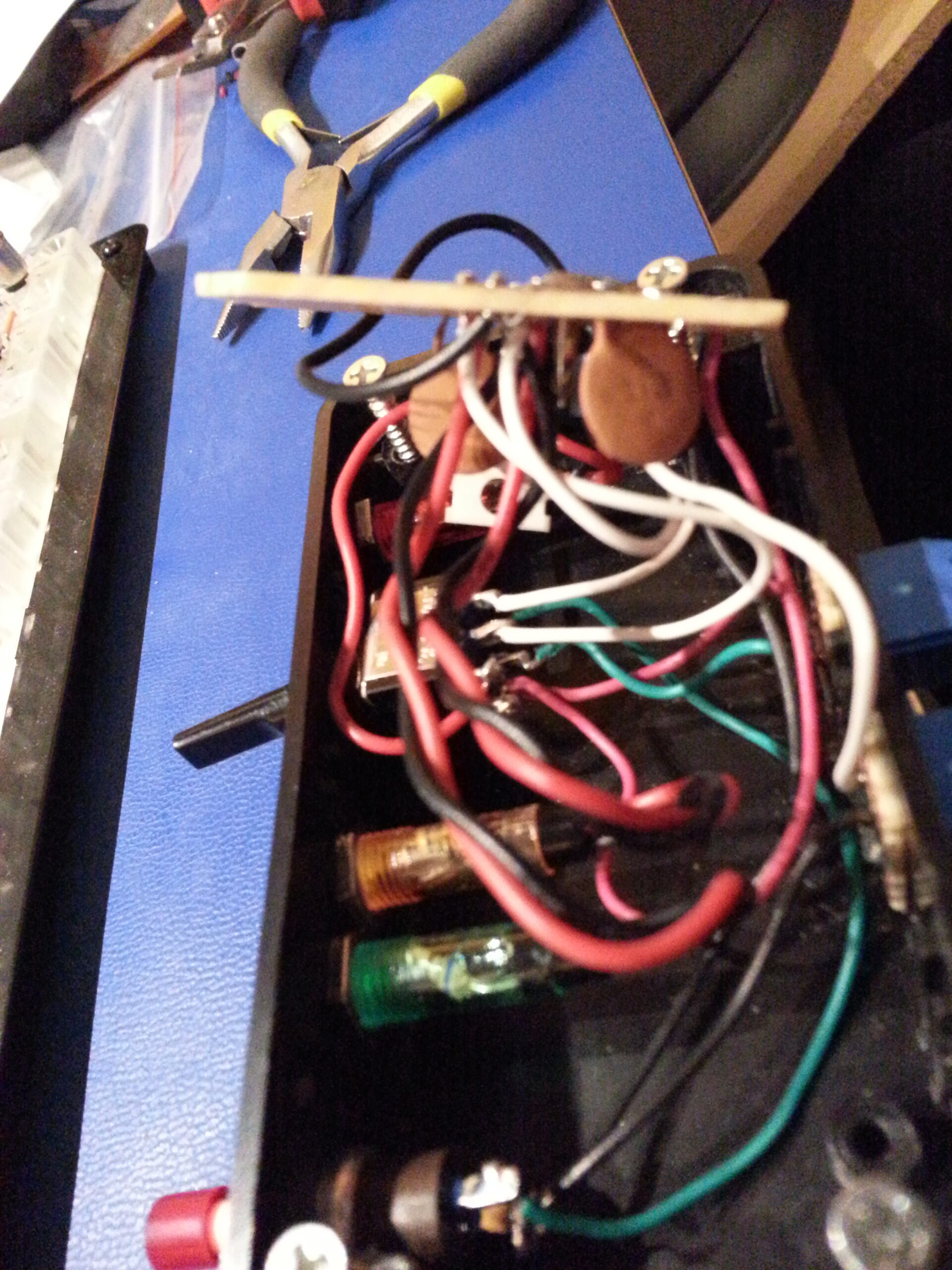
Finally I connected everything together and “stuffed” it into the box. I say “stuffed” because, well, it’s a sloppy jumble of wires going everywhere all kind-of crammed into that space. I thought about making it neater, or maybe doing a more sophisticated PCB that would eliminate much of the wiring, but in the end this was a quick-and-dirty job. As such, the extra length of the wires was needed in order to be able to assemble and disassemble the device for testing and/or changes.
If you make the wires too short then there’s no room for getting the circuit board into and out of the box without having to desolder something. The lead length also doesn’t matter too much in this case since it’s all low-voltage DC, and the heat dissipation requirements are vanishingly small – so “stuff” it is.
Make one connection at a time until everything is wired up, make a final test, then it’s stuff-in-a-box. 🙂
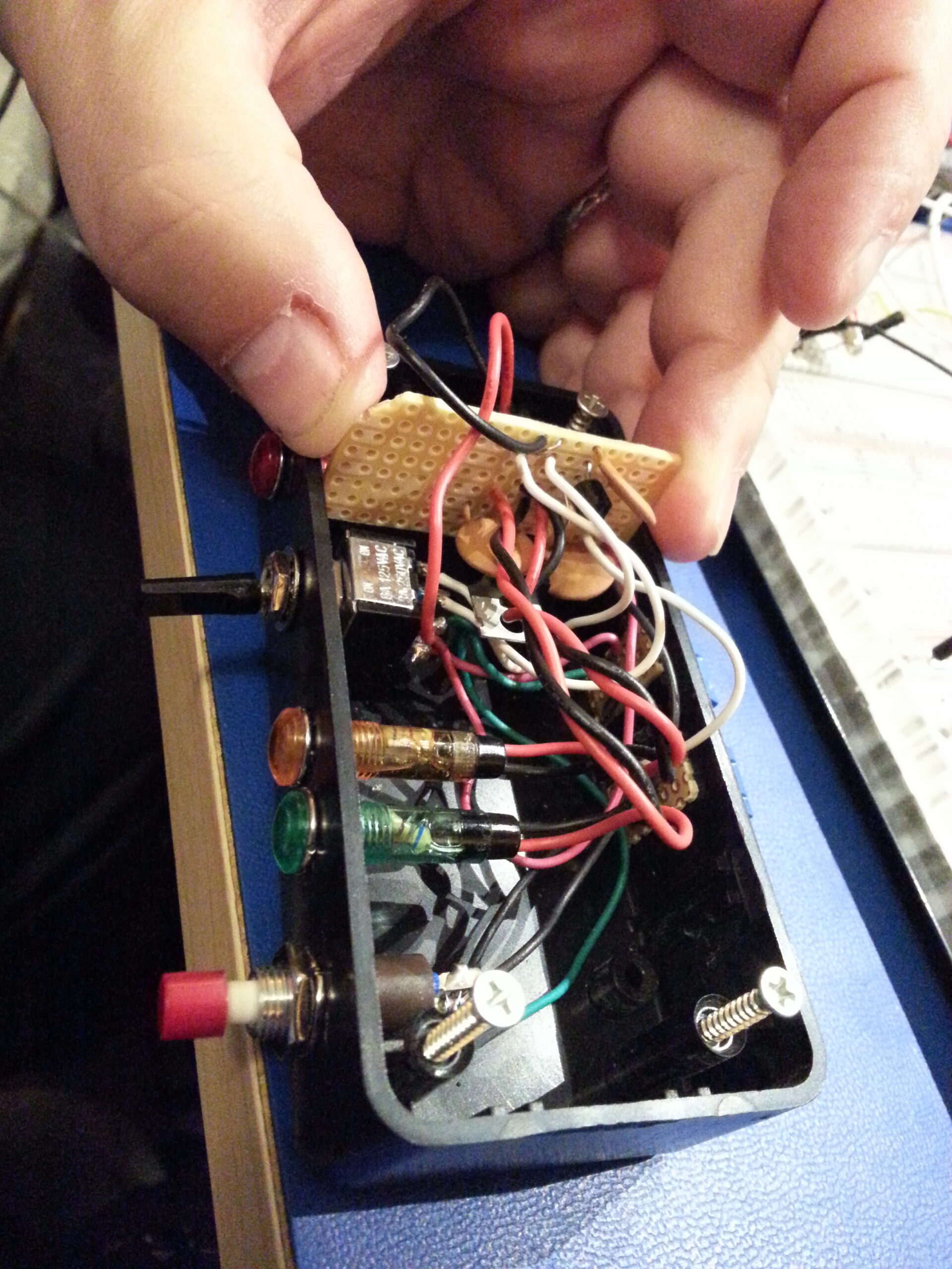
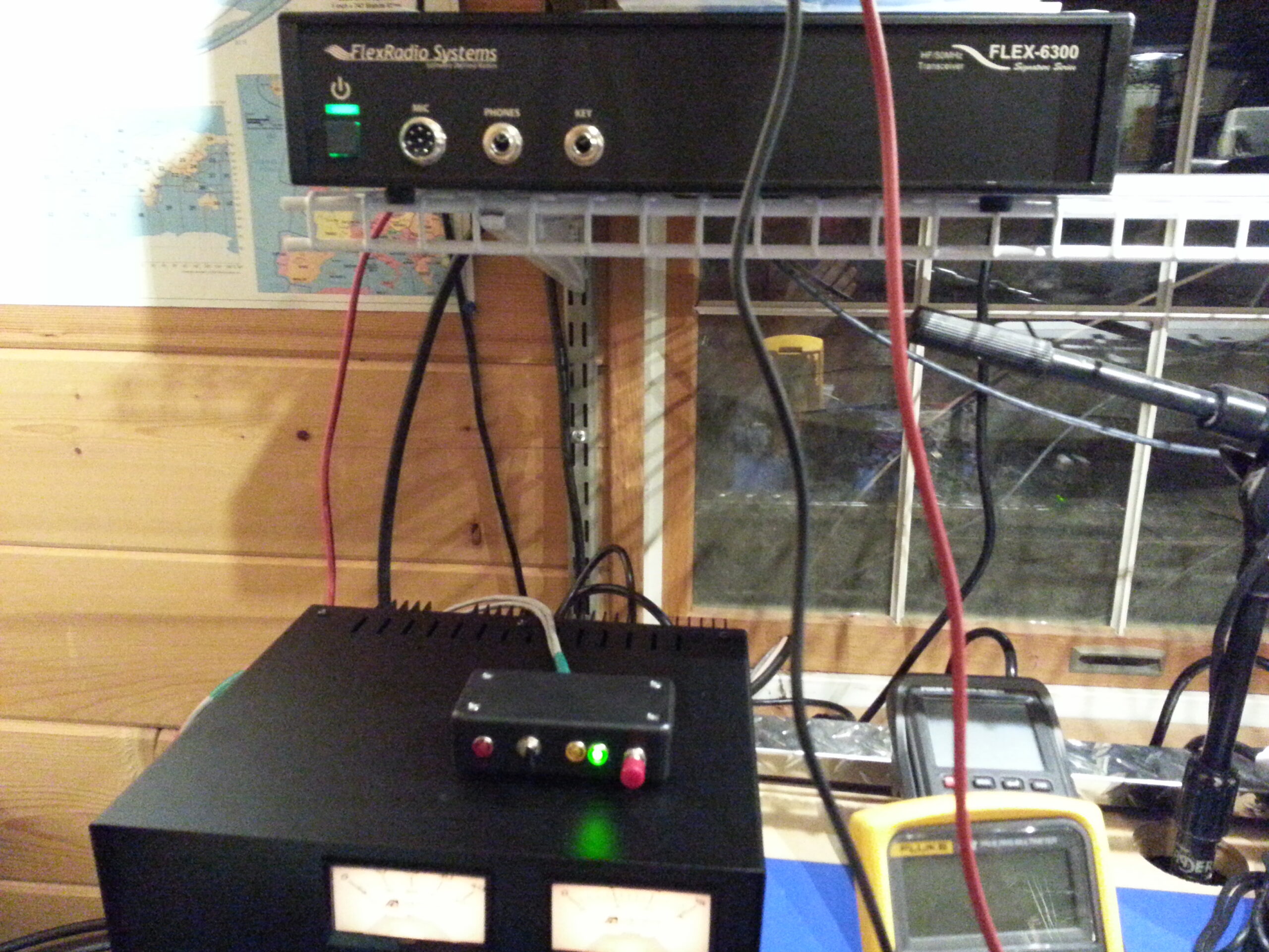
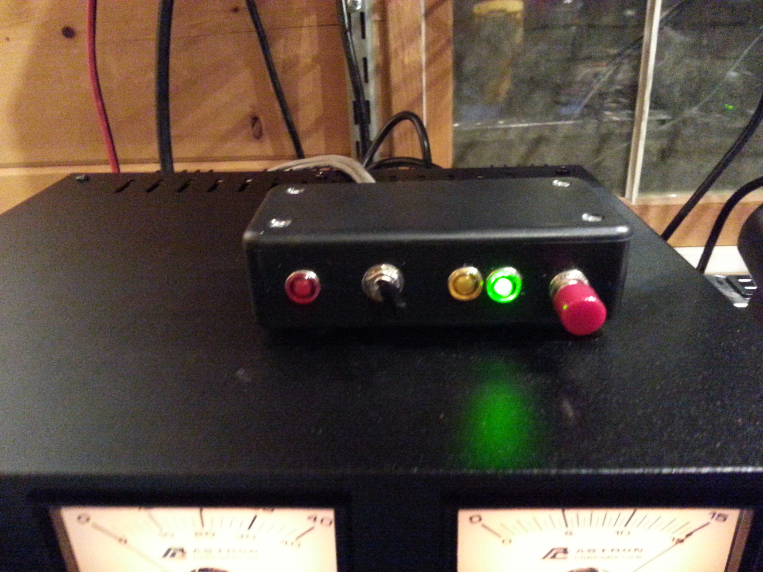
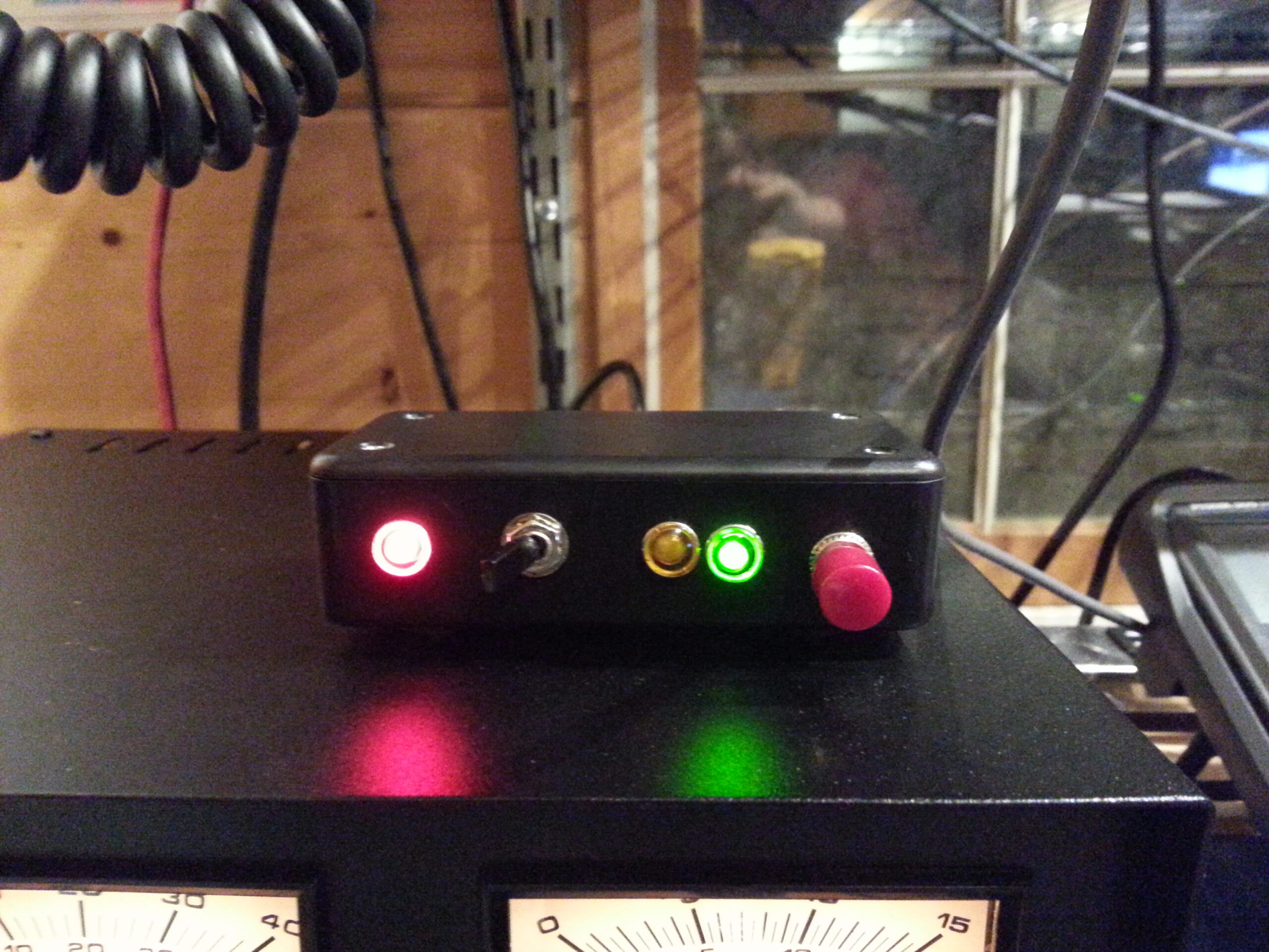
Once the lid is on and it’s up and running it’s a pretty solid and fairly professional presentation. The LEDs all work as expected, and the orientation of the toggle switch and the red “do-not-tune” light make the user interface intuitive. With the switch to the left (away from the controls) the red LED is on and the controls are locked. With the switch to the right (toward the controls) the tuner is free to tune and can be reset with the push-button.
I’ve thought about doing something more sophisticated with this… and maybe putting it in a heavier box; but ultimately it does the job, has been reliable, and there really isn’t more to do!
In future, maybe, if I built a feed-point tuner I might like to have it provide information about its’ tuning solution and even provide an analysis of the antenna… or perhaps also take commands to fine-tune the solution or act as a pre-selector … but that’s just me dreaming and NOT what this tuner does. This one is designed to be simple and reliable and it hits those marks very well.
This controller seems to hit those marks too — with just one extra blinkenlight 🙂